Chapter 5 Disassembly and Assembly
5-105
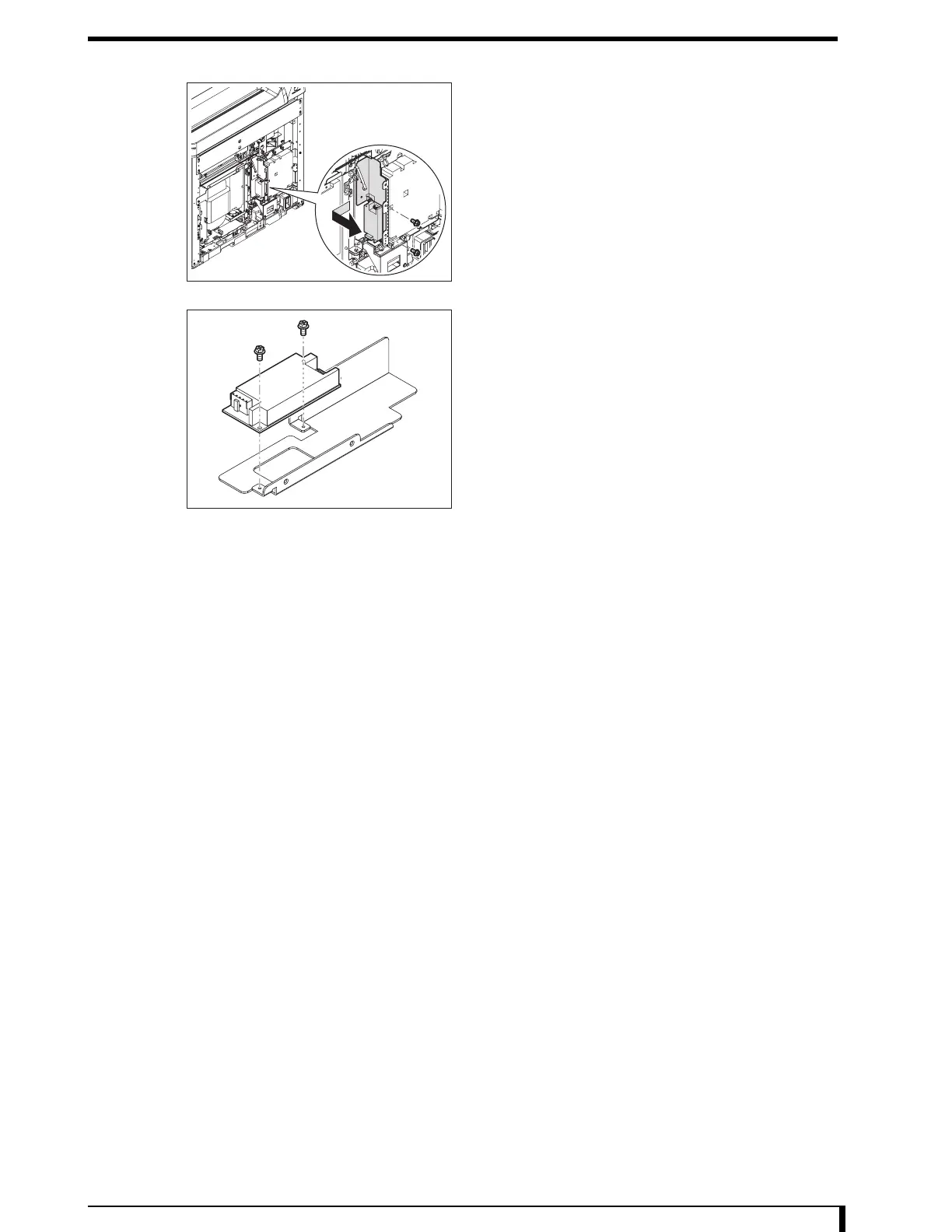
6 Remove the circuit board mount bracket.
•
2 hex/Phillips-head screws (M4 x 8)
7 Remove the standby power supply.
•
2 hex/Phillips-head screws (M3 x 6)
8 Install the new standby power supply.
•
2 hex/Phillips-head screws (M3 x 6)
9 See Step 6 to install the circuit board mount
bracket.
•
2 hex/Phillips-head screws (M4 x 8)
10 Connect the cables removed in Step 5 to the
standby power supply.
•
CN1 (JP23: cable)
• CN2 (JP26: cable)
11 Install the interlock relay 2 that was removed in
Step 4.
•
2 screws (M4 x 6)
12 Install the snap ties that was removed in Step 3.
13 Install the electric component mount panel that
was removed in Step 2.
•
8 hex/Phillips-head screws (M4 x 8)
14 See " Installation Procedures (Page 5-8)" in "5.2.3 Removing/Installing the Exterior Panel
and Insertion Unit" to install the first front panel.
Now, you have finished with the procedures to replace the standby power supply.