Contents
i
Contents
1
Introduction 1
2
Getting Started 1
2.1
Getting Started 1
3
Overview 3
3.1
About the Power Connect Feature 3
3.2
Shielded Twisted Pair (STP) / Unshielded Twisted Pair (UTP) 3
3.3
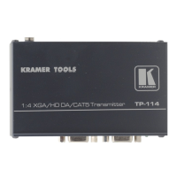
About the TP-114 4
3.4
Recommendations for Achieving the Best Performance 4
4
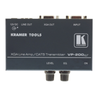
Your TP-114 1:4 XGA / HD DA /CAT5 Transmitter 5
5
Configuring a TP-114 XGA / HD Line Transmitter – DA System 7
5.1
Wiring the CAT5 LINE IN / LINE OUT RJ-45 Connectors 9
6
Technical Specifications 10
Figures
Figure 1: TP-114 1:4 XGA / HD DA /CAT5 Transmitter 5
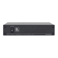
Figure 2: TP-114 1:4 XGA / HD DA /CAT5 Transmitter (Top Side Panel) 5
Figure 3: TP-114 1:4 XGA / HD DA /CAT5 Transmitter (Lower Side Panel) 5
Figure 4: TP-114 1:4 XGA / HD DA /CAT5 Transmitter (Underside Panel) 6
Figure 5: Configuring a TP-114 XGA / HD Line Transmitter – DA 8
Figure 6: CAT5 PINOUT 9
Tables
Table 1: TP-114 1:4 XGA / HD DA /CAT5 Transmitter Features 6
Table 2: TP-114 1:4 XGA / HD DA /CAT5 Transmitter (Underside Panel) Features 6
Table 3: CAT5 PINOUT 9
Table 4: Technical Specifications of the TP-114 (with 100m CAT5 cable) 10