KRAMER: SIMPLE CREATIVE TECHNOLOGY
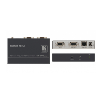
Your TP-114 1:4 XGA / HD DA /CAT5 Transmitter
6
Table 1: TP-114 1:4 XGA / HD DA /CAT5 Transmitter Features
# Feature Function
1 LINE OUT 1 RJ-45 Connector
Connects to
1
the LINE IN RJ-45 connector on the (first) TP-120 XGA
Line Receiver
2
2 LINE OUT 2 RJ-45 Connector
Connects to
1
the LINE IN RJ-45 connector on the (second) TP-120
XGA Line Receiver
2
3 LINE OUT 3 RJ-45 Connector
Connects to
1
the LINE IN RJ-45 connector on the (third) TP-120
XGA Line Receiver
2
4 LINE OUT 4 RJ-45 Connector
Connects to
1
the LINE IN RJ-45 connector on the (fourth) TP-120
XGA Line Receiver
2
5 12V DC +12V DC connector for powering the unit
6 XGA IN HD15F Connector Connect to the XGA source
7 XGA OUT HD15F Connector Connect to the XGA acceptor
8 ON LED Illuminates when receiving power
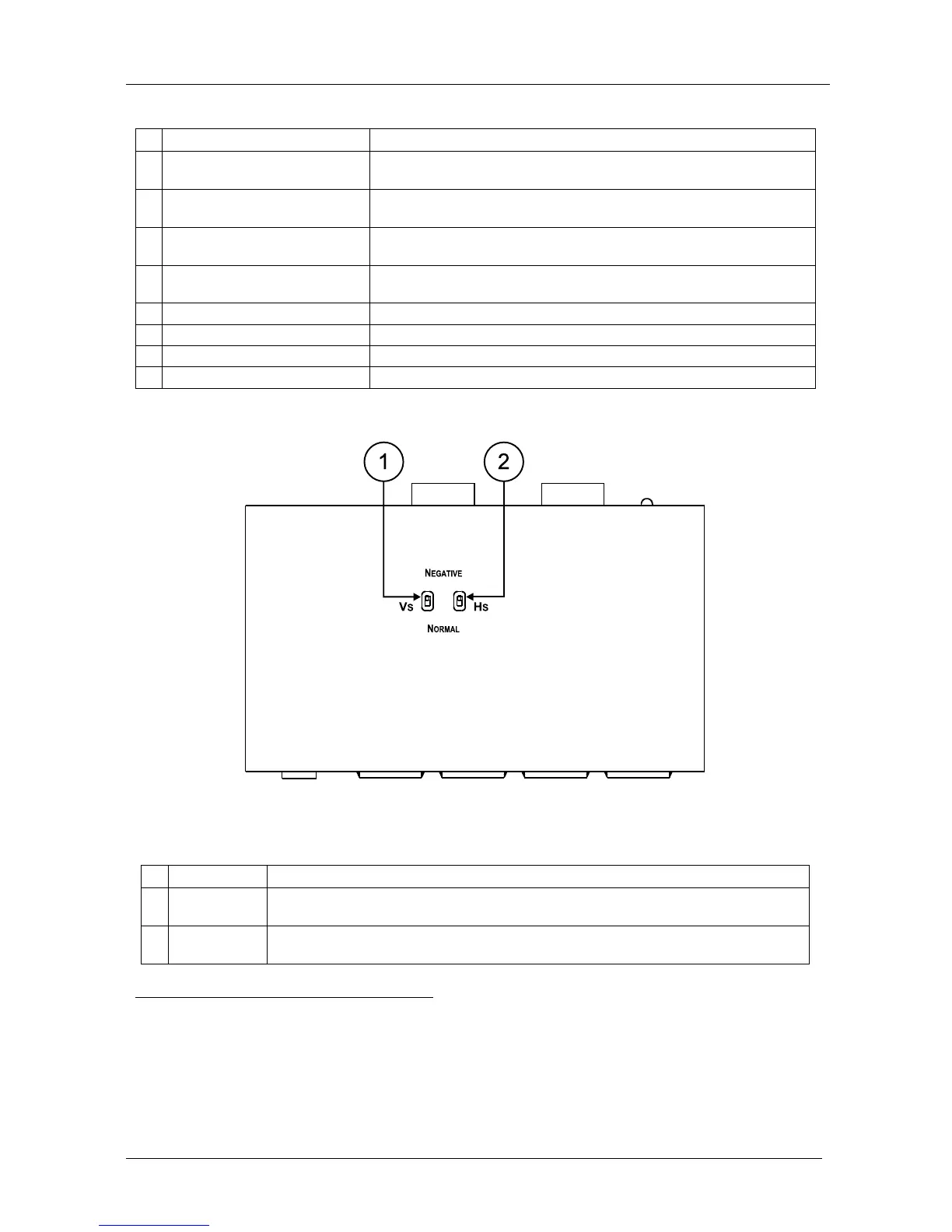
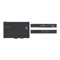
Figure 4 and Table 2 define the TP-114 underside panel:
Figure 4: TP-114 1:4 XGA / HD DA /CAT5 Transmitter (Underside Panel)
Table 2: TP-114 1:4 XGA / HD DA /CAT5 Transmitter (Underside Panel) Features
# Feature Function
1 VS Switch Slide the switch up
3
to change the VS polarity to NEGATIVE polarity
4
; slide the
switch down to NORMAL to retain the polarity
2 HS
Switch Slide the switch up
3
to change the HS polarity to NEGATIVE polarity
4
; slide the
switch down to NORMAL to retain the polarity
1 Using a UTP CAT5 cable with RJ-45 connectors at both ends (the PINOUT is defined in Table 3 and Figure 6)
2 Refer to the separate user manual: PT-110, PT-120, TP-120, WP-110, which can be downloaded from the Internet at this
URL: http://www.kramerelectronics.com. Also, see the example illustrated in Figure 5
3 By default, both switches are set in the down position
4 Downgoing syncs