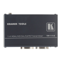
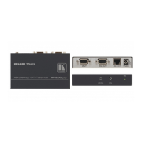
Configuring a TP-114 XGA / HD Line Transmitter – DA System
7
5 Configuring a TP-114 XGA / HD Line Transmitter – DA System
You can use the TP-114 with four TP-120 units
1
to configure a 1:4 XGA / HD
DA /CAT5 Transmitter system. This will let you transmit a computer
graphics / HD signal to four displays via long line CAT5 UTP cabling.
To connect the TP-114 to four TP-120 units, as the example in Figure 5
illustrates, do the following:
1. On the TP-114, connect the XGA / HD source (for example, a computer
graphics / HD source) to the XGA IN HD15F connector, and connect the line
output RJ-45 connector
2
:
OUT 1 connector to the LINE IN RJ-45 connector on the first TP-120
OUT 2 connector to the LINE IN RJ-45 connector on the second TP-120
OUT 3 connector to the LINE IN RJ-45 connector on the third TP-120
OUT 4 connector to the LINE IN RJ-45 connector on the fourth TP-120
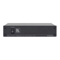
2. On the four TP-120 units, connect the:
XGA OUT HD15F connector of the first TP-120 unit to the XGA / HD
acceptor (for example, Display 1)
XGA OUT HD15F connector of the second TP-120 unit to the XGA /
HD acceptor (for example, Display 2)
XGA OUT HD15F connector of the third TP-120 unit to the XGA / HD
acceptor (for example, Display 3)
XGA OUT HD15F connector of the fourth TP-120 unit to the XGA / HD
acceptor (for example, Display 4)
3. On each Kramer TOOL, connect the 12V DC power adapter to the power
socket and connect the adapter to the mains electricity.
The signal from the XGA source is transmitted via the CAT5 cables,
decoded and converted at the each of the XGA OUT HD15F connectors
to the XGA acceptors.
4. On the TP-120 units, if necessary:
Set the H SYNC and V SYNC switches
3
on the underside
Adjust
4
the video output signal level and/or cable compensation
equalization level
1 Refer to the separate user manual: PT-110, PT-120, TP-120, WP-110, which can be downloaded from the Internet at this
URL: http://www.kramerelectronics.com
2 Via UTP cabling (with a range of more than 300ft (>100m)). For details of how to wire a CAT5 LINE IN / LINE OUT
RJ-45 connector, see section 5.1
3 By default, both switches are set down (for negative V SYNC and H SYNC polarity)
4 Use a screwdriver to carefully rotate the trimmer, adjusting the appropriate level