KRAMER: SIMPLE CREATIVE TECHNOLOGY
Your TP-141 / TP-142
8
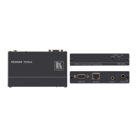
Table 3: TP-142 XGA/Audio Line Receiver (Topside) Features
# Feature Function
1 12V DC +12V DC connector for powering the unit
2 S/PDIF RCA connector Connects to the digital audio acceptor
3
AUDIO
OUT
ANALOG 3.5mm Mini
Jack
Connects to the analog audio acceptor
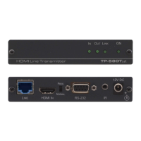
4 LINE IN RJ-45 Connector
Connects to
1
the TP-141
5 XGA OUT 15-pin HD F Connector Connects to the XGA acceptor
6 LINK LED Illuminates when receiving the correct input signal
7 LEVEL Trimmer Adjusts the output signal level
8 EQ.
2
Trimmer Adjusts
3
the cable compensation equalization level
9 ON LED Illuminates when receiving power
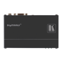
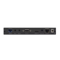
4.2.2 Your TP-142 XGA/Audio Line Receiver (Underside)
Figure 4 and Table 4 define the underside of the TP-142 XGA/Audio Line
Receiver:
Figure 4: TP-142 XGA/Audio Line Receiver (Underside)
Table 4: TP-142 XGA/Audio Line Receiver (Underside) Features
# Feature Function
10 HS Switch To set H SYNC to positive polarity, slide the switch to the right
4
;
to set the H SYNC to negative polarity, slide the switch to the left
11 VS Switch To set V SYNC to positive polarity, slide the switch to the right
4
;
to set the V SYNC to negative polarity, slide the switch to the left
12 XGA/Video Switch To set for any video signal, such as HDTV, slide the switch to VIDEO;
to set for a computer graphics signal, slide the switch to XGA
1 Using a UTP CAT 5 cable with RJ-45 connectors at both ends (the PINOUT is defined in Figure 6 and Table 5.)
2 Degradation and VGA/XGA signal loss can result from using long cables (due to stray capacitance), sometimes leading to a
total loss of sharpness in high-resolution signals
3 Use a screwdriver to carefully rotate the trimmer, adjusting the appropriate level
4 By default, both switches are set to the left (for a negative V SYNC and H SYNC polarity)