KRAMER: SIMPLE CREATIVE TECHNOLOGY
Your TP-141 / TP-142
6
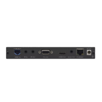
Table 1: TP-141 XGA/Audio Line Transmitter Features
# Feature Function
1 12V DC +12V DC connector for powering the unit
2 AUDIO IN 3.5mm Mini Jack Connects to the audio source
3 LINE OUT RJ-45 Connector
Connects to
1
the LINE IN RJ-45 connector on the TP-142
XGA/Audio Line Receiver
4 XGA IN 15-pin HD F Connector Connect to the XGA source
5 ON LED Illuminates when receiving power
4.1.2 The TP-141 Internal Polarity Switches
Figure 2 and Table 2 define the internal sync polarity switches inside the
TP-141.
Note: If adjustment is necessary, open the TP-141 unit to gain access to the
Vs and Hs Polarity switches. After setting the switches, close the TP-141
unit.
NORM.
NE G.
Figure 2: TP-141 Internal Polarity Switches
Table 2: Features of the TP-141 Internal Polarity Switches
Feature Function
VS Switch To set V SYNC to negative polarity (NEG), slide the switch down
2
;
to set V SYNC to its input polarity (NORM), slide the switch up
HS Switch To set H SYNC to negative polarity (NEG), slide the switch down
2
;
to set H SYNC to its input polarity (NORM), slide the switch up
1 Using a UTP CAT 5 cable with RJ-45 connectors at both ends (the PINOUT is defined in Figure 6 and Table 5)
2 By default, both switches are set down (for a negative V SYNC and H SYNC polarity)