5 Connecting the XGA/Audio Line Transmitter/Receiver
You can use the TP-141 and TP-142 to configure an XGA/Audio Line-
to-Twisted Pair Transmitter and Receiver system.
To connect the TP-141 XGA/Audio Line Transmitter with the TP-142
XGA/Audio Line Receiver, as illustrated in Figure 5, do the following:
1. On the TP-141, connect the XGA source (for example, the graphics card of
a laptop) to the XGA INPUT 15-pin HD (F) connector.
2. Connect an audio source to the AUDIO IN 3.5mm mini jack, for example,
using a Kramer C-GMA/GMA cable (VGA 15-pin HD (M) +audio jack to
VGA 15-pin HD (M) +audio jack)
1
.
Alternatively, you can connect an XGA source to the XGA INPUT 15-pin
HD (F) connector, and a separate audio source to the AUDIO IN 3.5mm
mini jack.
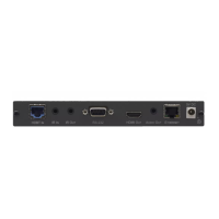
3. On the TP-142, connect the XGA OUT 15-pin HD (F) connector to the
XGA acceptor (for example, a display).
4. Connect the AUDIO OUT S/PDIF RCA connector to the digital audio
acceptor (for example, an AV receiver).
5. Connect the ANALOG 3.5mm mini jack to the analog audio acceptor (for
example, a stereo audio recorder).
6. Connect the LINE OUTPUT RJ-45 connector on the TP-141 to the LINE
IN RJ-45 connector on the TP-142, via CAT 5 (UTP or STP) cabling, (see
connector pinouts in section 5.1).
7. Connect the 12V DC power adapter to the power socket of either the
TP-141 or the TP-142 and connect the adapter to the mains electricity. The
Power Connect feature feeds power to the second device. If the second
device does not power on due to a long line, connect a 12V DC power
adapter to the second device as well.
8. On the TP-142:
Adjust
2
the video output signal level and/or cable compensation
equalization level, if required
If necessary, set the H SYNC and V SYNC switches
3
, on the
underside
1 Not supplied. The complete list of Kramer cables is on our Web site at http://www.kramerelectronics.com
2 Use a screwdriver to carefully rotate the trimmer, adjusting the appropriate level
3 By default, both switches are set to the left (for negative V SYNC and H SYNC polarity)