Your HDMI Line Transmitters/Receiver
4.2 Your TP-582T HDMI Switcher/Line Transmitter
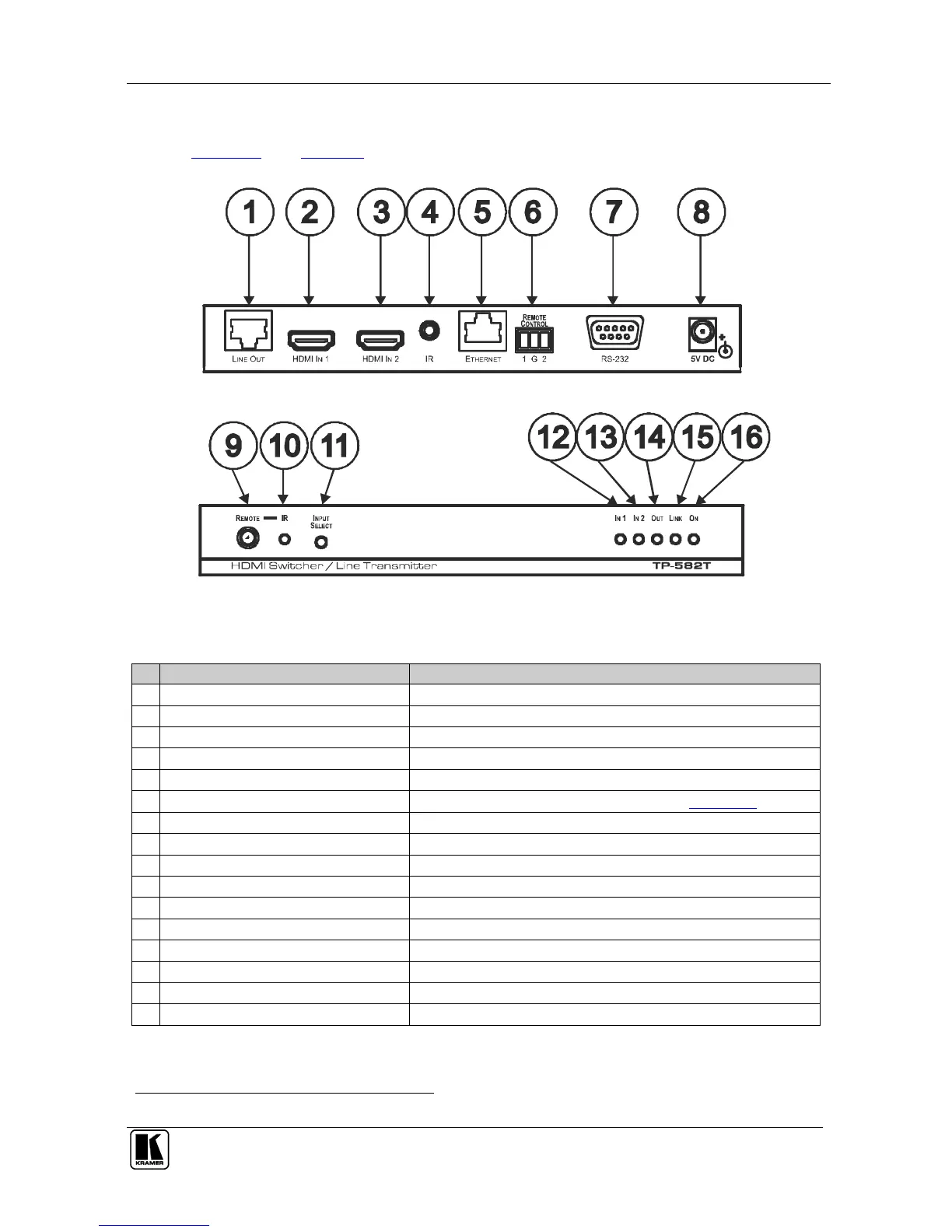
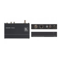
Figure 2 and Table 2 define the TP-582T:
Figure 2: TP-582T HDMI Switcher/Line Transmitter
Table 2: TP-582T HDMI Switcher/Line Transmitter Features
Connects to the CAT 5 IN RJ-45 connector on the TP-582R
Connects to the HDMI source 1
Connects to the HDMI source 2
IR 3.5mm Mini Jack Connector
Connects to an external infrared transmitter/sensor (receiver)
REMOTE CONTROL Terminal Block
Connects to contact closure switches (see Section 5.4)
RS-232 9-pin D-sub Connector
Connects to an RS-232 port
+5V DC connector for powering the unit
Senses commands from the Kramer IR remote control device
1
Lights when an infrared signal is detected
Press to toggle between HDMI inputs
Lights when the HDMI 1 input device is connected
Lights when the HDMI 2 input device is connected
Lights when an HDMI output device is detected
Lights when the TP connection is active
Lights when receiving power
Note that the IR sensor is only used to select the TP-582T inputs. These IR signals cannot be transmitted to the TP-582R