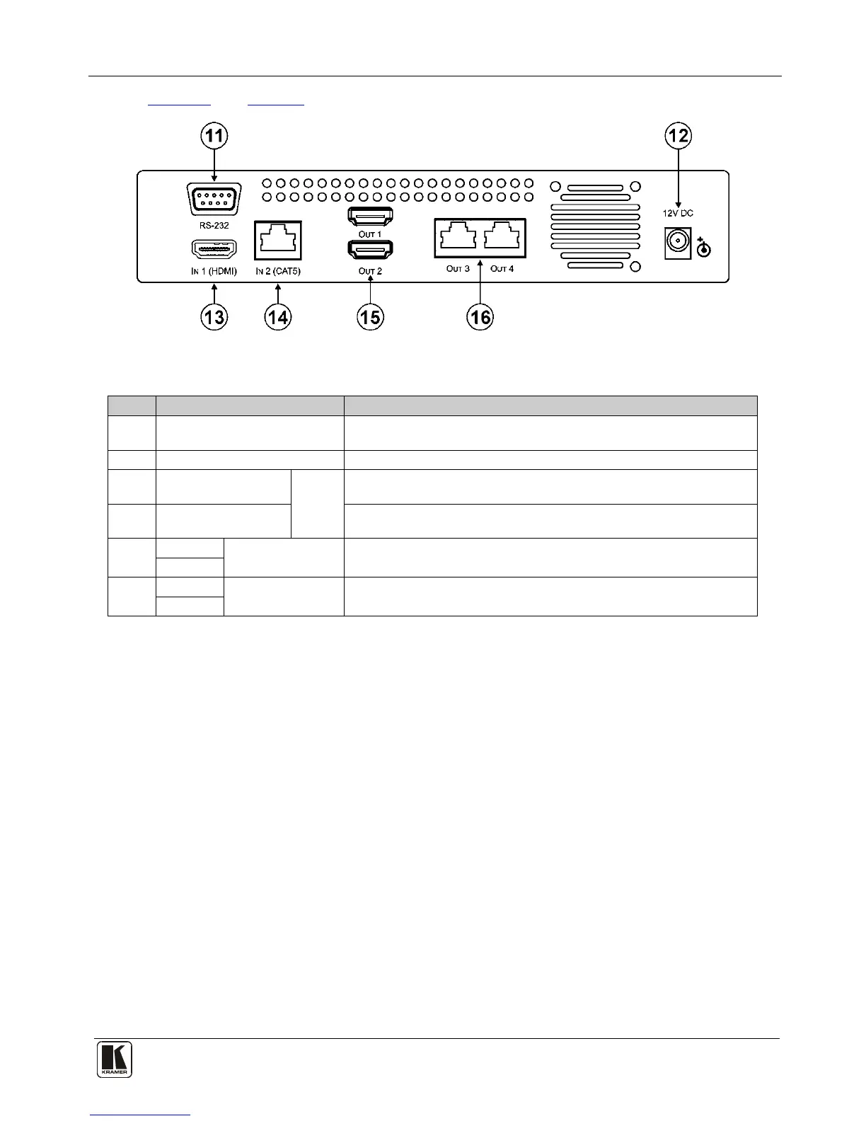
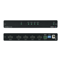
Figure 2 and Table 2 define the rear panel of the VM-114H2C.
Figure 2: VM-114H2C Rear Panel
Table 2: VM-114H2C Rear Panel Features
# Feature Function
11 RS-232 9-pin D-sub (F)
Connector
Connect to a PC or remote controller
12 12V DC Power Connector Connect to the +12V DC power adapter, center pin positive
13 IN1 (HDMI) Input
HDMI Connector
Inputs
Connect to an HDMI source
14 IN2 (CAT5) Input
RJ-45 Connector
Connect to a TP source (for example, PT-571 HDMI Line Transmitter,
VM-114H2C or VM-114H4C)
15 OUT 1
HDMI Output
Connectors
Connect to the HDMI acceptors
OUT 2
16 OUT 3
TP RJ-45 Output
Connectors
Connect to the TP acceptors (for example, PT-572+ HDMI Line Receiver,
VM-114H or VM-114H4C)
OUT 4