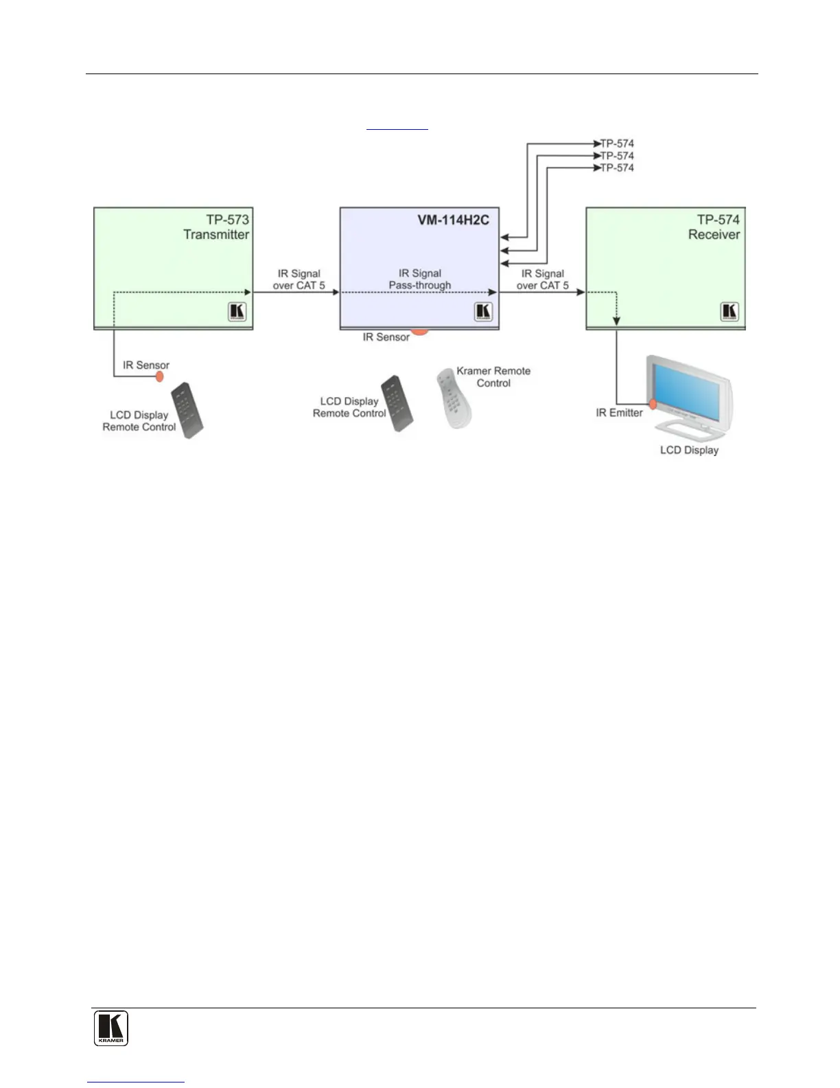
5.4.2.2 IR Local Control and Pass-through Example Two
The configuration is shown in Figure 6.
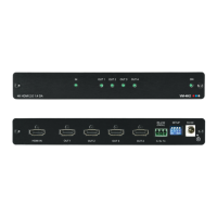
Figure 6: VM-114H2C IR Control and Pass-through Example Two
An IR sensor is connected to the TP-573 transmitter.
An LCD display is connected to the TP-574 receiver via an IR emitter.
Both the TP-573 and the TP-574 are connected to the VM-114H2C via TP
cabling.
To control the LCD display, point the LCD display remote control either at the
TP-573 IR sensor or at the VM-114H2C IR sensor. To control the VM-114H2C,
point the Kramer remote control at the VM-114H2C IR sensor.