R
DB110 Electric - Adjustments
10.
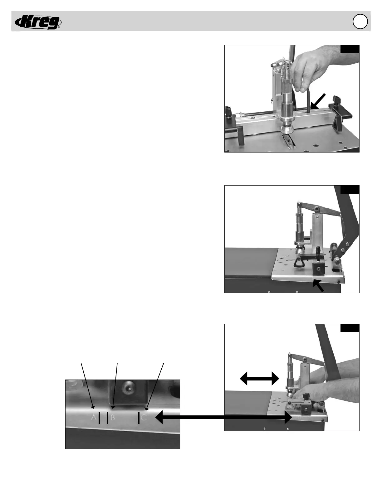
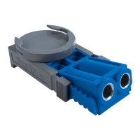
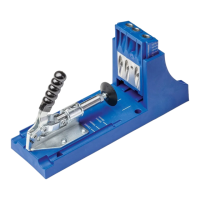
Fig. 6A
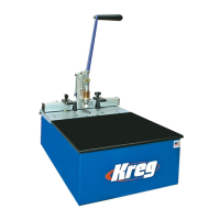
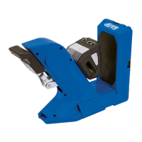
Fig. 6B
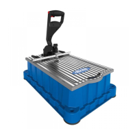
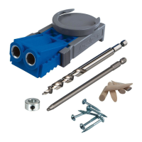
Fig. 6C
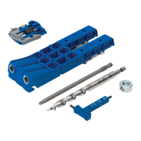
Move the Fence to the setting outlined for the
thickness of the material to be drilled.
The FOREMAN ships from the factory with the Fence
in the 3/4” setting.
Sockethead Cap Screws hold the EZ DB Fence
in position.
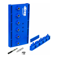
Reference Scale (shown in black to show detail)
Adjusting the EZ DB Fence Setting
The Fence can be adjusted to align the pocket hole to the center of
material of different thicknesses. When adjusting the Fence make sure
that the Fence remains perpendicular to the Guide Plate. A Reference
Scale has been provided to approximate the fence setting for 1/2”, 3/4”,
and 1-1/2” thick material. These correspond to the “A”, “B”, and “C” lines
on the Reference Scale.
Step 1. Loosen the (2) Socket-head Cap Screws contained below the
surface of the Fence as shown in fi g. 6A.
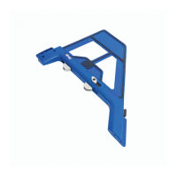
Step 2. Align the Fence perpendicular to the Guide Plate for the
setting that corresponds to the material thickness as
shown in fi g. 6C.
Step 3. Tighten the (2) Socket-head Cap Screws to lock the Fence
into position as shown in fi g 6A.
A
B
C
A = 1/2” B = 3/4” C = 1-1/2”