Operating Instructions 7
Electrical connection
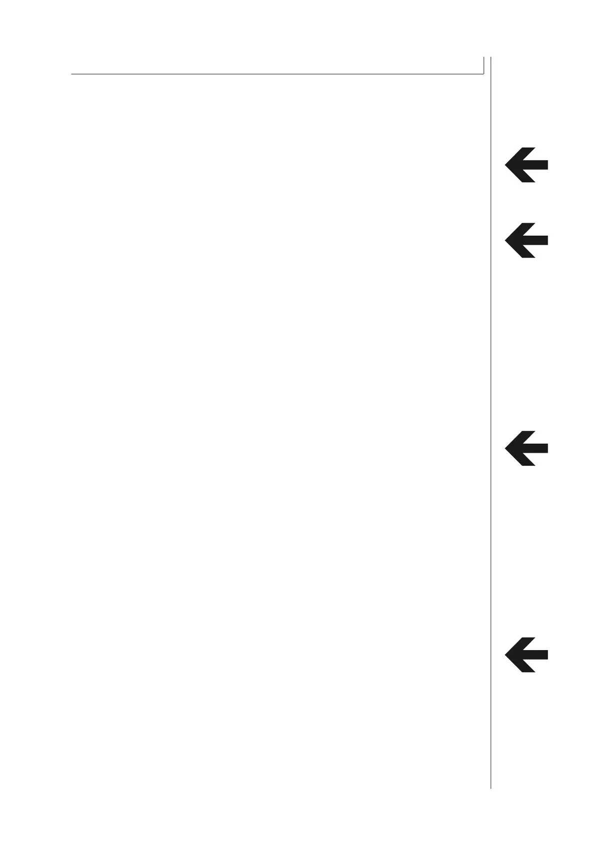
The chiller is ready for connection and should only be connected to a three phase current network
(mains voltage refer to technical data).
The power supply has to be connected in a right handed rotatory fi eld. In order to confi rm the
correct connection the direction of rotation of the fan motor must turn in the same direction as the
arrow.
All electrical connections in the switch board are to be tightened prior to commissioning.
Incorrect connection of power supply and incorrect power supply will cancel the
manufacturers liability for subsequent damage.
Hydraulic connection
After completing the electrical connection it is necessary to connect the Chiller to the consumer VIA
fl exible or fi xed pipes.
Selection of materials of pipes. PVC, Plastic, Stainless Steel, Copper and Brass are permissible.
Note: Mild Steel and Galvanized Steel is not permissible.
Selection of cross – section of pipes (for advise please refer to manufacturer).
Insulated pipes are to be used if the distance between the chiller and the consumer is greater
than 5 m.
Refer to technical data (pump diagram) for fl ow rate and pressure available from the chiller.
Before starting up it is always necessary to prime the pump with the medium to be transported.
(refer to BLEEDING OF PUMP in this chapter).
If the consumer is placed on a higher level than the chiller unit, a non-return valve has to be installed
in the water outlet as well as an solenoid valve has to be installed in the water inlet.
Connect water inlet port to cnsumer return line.
Connect water outlet port to consumer inlet line.
Connect water supply port to tap/fresh water supply.
Please test fl oat valve adjustment (option). Float valve is factory adjusted at 3 bar water pressure.
Incorrect hydraulic installation will cancel the manufacturers liability for subsequent damage.
3 INSTALLATION AND INITIAL OPERATION