EasyManua.ls Logo

KROHNE IFC 020 K User Manual

KROHNE IFC 020 K
79 pages
To Next Page IconTo Next Page
Page #1 background imageLoading...
Page #1 background image
Installation and
operating instructions
IFC 020 K
IFC 020 F
IFC 020 E
Signal converters for
electromagnetic flowmeters
DIN A4: 7.10003.32.00
©
KROHNE 12/2002 US size: 7.10003.72.00
GR
Applicable to
Software Versions
IFC 020 K and
IFC 020 F
No. 3170330200
IFC 020 E
No. 3175870200
How to use these Instructions
The flowmeters are supplied ready for operation.
The primary head must be installed in the pipeline as described in the installation
instructions inside the packing of the primary head.
Installation location and connection to power (Section 1) Pages 1/1-1/8
Electrical connection of outputs and inputs (Section 2) Pages 2/1-2/4
Factory settings and start-up (Section 3) Pages 3/1-3/2
Power the flowmeter. THAT’S ALL. The system is operative.
Pull-out
Condensed Instructions
Variable area flowmeters
Vortex flowmeters
Flow controllers
Electromagnetic flowmeters
Ultrasonic flowmeters
Mass flowmeters
Level measuring instruments
Communications technology
Engineering systems & solutions
Switches, counters, displays and recorders
Heat metering
Pressure and temperature

Table of Contents

Question and Answer IconNeed help?

Do you have a question about the KROHNE IFC 020 K and is the answer not in the manual?

KROHNE IFC 020 K Specifications

General IconGeneral
BrandKROHNE
ModelIFC 020 K
CategoryMeasuring Instruments
LanguageEnglish

Summary

How to Use These Instructions

Installation location and connection to power (Section 1)

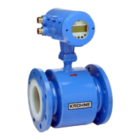
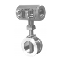
Details on flowmeter installation location and power connection.

Electrical connection of outputs and inputs (Section 2)

Procedures for connecting outputs and inputs to the flowmeter.

Factory settings and start-up (Section 3)

Information on factory settings and initial start-up procedures.

Part A System Installation and Start-up

1 Electrical Connection: Power Supply

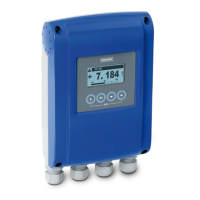
Instructions for connecting the power supply to the signal converter.

2 Electrical Connection of Outputs and Inputs

Guidelines for connecting outputs and inputs to the signal converter.

3 Start-up Procedures

Steps for powering on, measurement, and factory settings.

Part B IFC 020_/D Signal Converter Operation and Functions

4 Operation of the Signal Converter

Details on operating the signal converter, including control concepts and keys.

5 Description of Functions

Explanation of various functions like range, time constant, and outputs.

Part C Special Applications, Functional Checks, Service, and Order Numbers

6 Special Applications

Information on special applications like HART and RS 485 interfaces.

7 Functional Checks

Procedures for performing functional checks and tests on the device.

8 Service Procedures

Guidance on service work, including illustrations and replacement procedures.

9 Order Numbers

List of order numbers for electronic units and power fuses.

Part D Technical Data, Measuring Principle, and Block Diagram

10 Technical Data

Comprehensive technical specifications including ranges, errors, and dimensions.

11 Measuring Principle

Explanation of the electromagnetic induction principle used for flow measurement.

12 Block Diagram – Signal Converter

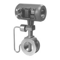
Diagram illustrating the internal structure and components of the signal converter.

Returning Flowmeters for Testing or Repair

SPECIMEN Certificate for Return

Template certificate required for returning flowmeters for service.

Related product manuals