31
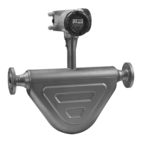
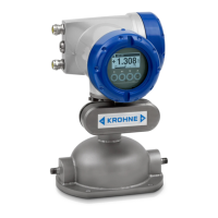
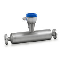
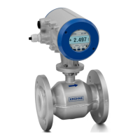
OPTIMASS
4
ELECTRICAL CONNECTIONS
4.1 General
• The MFC 300F mass flow converter or OPTIMASS / OPTIGAS x300C mass flow meter must
be included in the equipotential bonding system of the installation using the equipotential
bonding terminal on the mass flow converter housing wall bracket or mass flow meter
housing mounting stem respectively.
• The covers of the housing electronics compartment and the housing itself are provided with
a "flameproof" thread. The f "flameproof" thread is a tight fit due to explosion proof
requirements. Screw the cover on or off with care and never use excessive force!
• Keep the threads free of dirt and apply Teflon grease (eg. NONTRIBOS
®
type Li EP2). The
grease will help to prevent the threads from locking due to corrosion
• To open the covers, remove the hexagonal "retention" lock using a No. 3 Allen key. After
closing the covers, refit the "retention lock".
EElleeccttrroonniiccss ccoommppaarrttmmeenntt::
• Allow the electronics to de-energize before opening the electronics compartment: T6: at
least 35 min., T5: at least 10 min.
TTeerrmmiinnaall ccoommppaarrttmmeenntt::
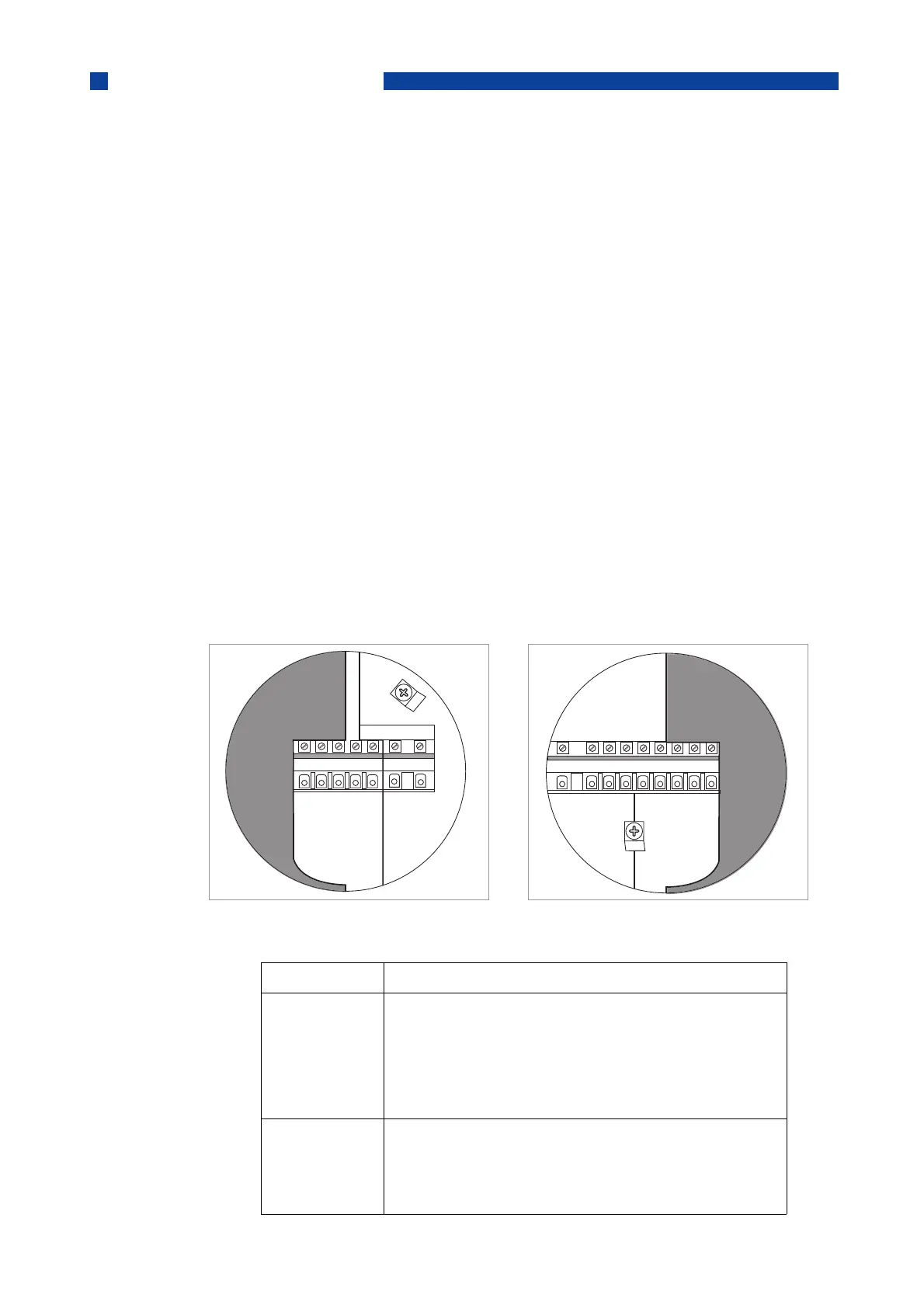
• The terminal compartment can be opened in hazardous areas, for a short period of time
(eg. to check wiring configuration) with the power supply connected, where:
a) the terminal compartment has an ignition protection type “increased safety” (standard) and
b) the I/O circuits have an ignition protection type “intrinsic safety” and
c) the cover for the power supply terminals (L,N) is closed (see illustration)
Work on I/O terminals A-D can be carried out with the power supply connected, provided that
the regulations on intrisically safe circuits are followed
As soon as the work has been completed, the cover must be replaced and the retention lock re-fitted.
1 Electrical Connections
2 I/O Connections
12
TTeerrmmiinnaall FFuunnccttiioonn,, eelleeccttrriiccaall ddaattaa
L, N
L+, L-
Connection for mains, always non-Ex i
100..230 VAC, +10%/-15%, 22 VA
12..24 V DC, +30%/-25%, 12 W
24 VAC, +10%/-15%, 22VA
24 VDC, +30%/-25%, 12W
Um = 253 V
A, A-,A+
B, B-
C, C-
D, D-
Connection for signal I/Os (PELV circuits), non-Ex I or Ex
I, are dependent on specific version of the MFC300 con-
verter ordered.
Consult the table with CG32 numbers below for details
AD OPTIMASS 300_010 Haz Areas Rev 01.qxp 05/03/2014 13:25 Page 31