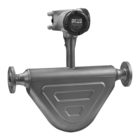
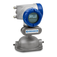
Installation and Operating Instructions OPTIMASS
75
Testing the pulse output Fct. 2.5
To test the pulse output, connect an external counter to the output terminals. When testing the pulse
output, the operator has the choice of the following pulse widths: 0.4 ms, 1.0 ms, 10.0 ms, 100.0 ms and
500 ms.
The operator should choose the pulse width that best matches the performance of his external pulse
counter.
Connect a pulse counter to the impulse output and proceed as follows:
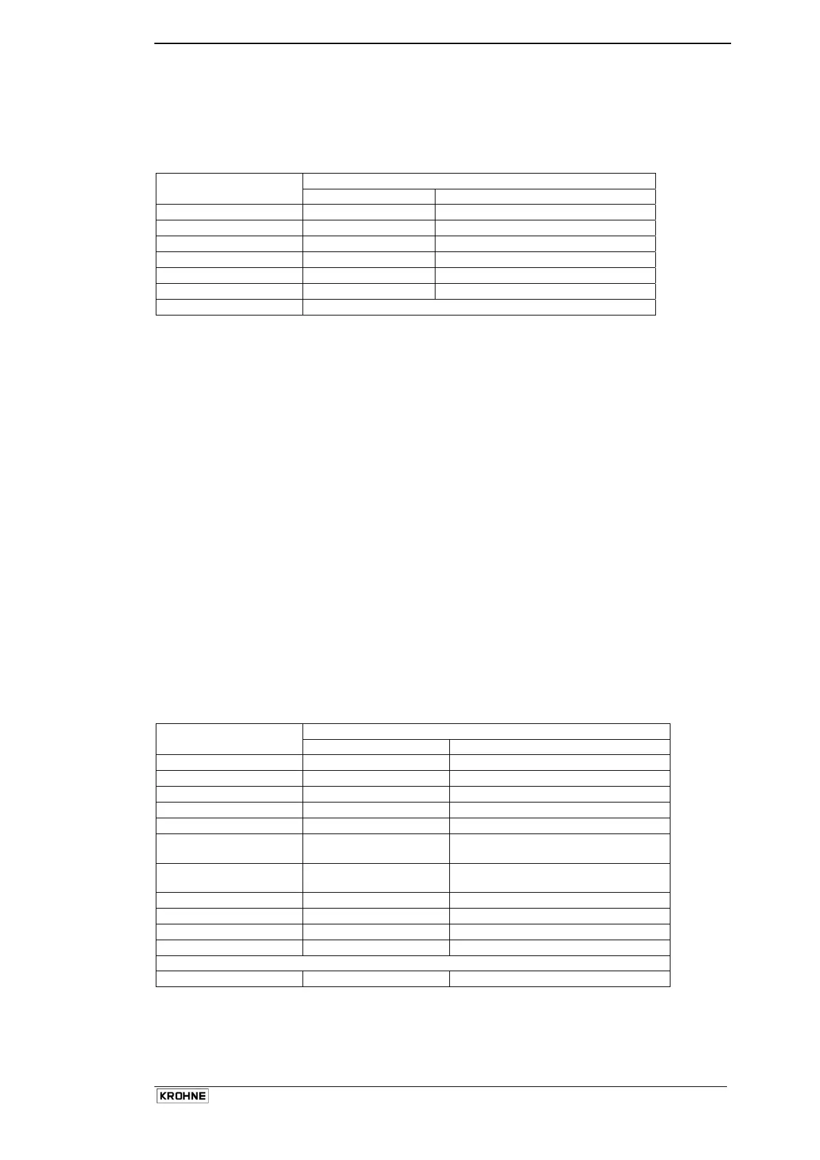
Display
Key
Line 1 Line 2
→↑
Fct. (2) TEST
→
Fct. 2.(1) DISPLAY
↑ x 4
Fct. 2.(5) Pulse out
→
SURE (NO)
↑
SURE (YES)
↵
Select pulse width with ↑ key
↵
Start test pulse output
The meter now issues a stream of pulses with the set width. The running total of pulses sent is shown on
the display. The test stops when either 100,000 pulses have been sent or the operator presses the ↵ key.
A connected counter will now count. Press ↵ to stop the counting. The meter display and counter should
have matching totals.
If the counter reads a smaller number than the actual number of pulses sent, or the frequency meter under
reads, then this indicates that a weak signal is reaching the frequency meter/pulse counter. In this case try
the following suggestions:
• Decrease the external pull-up resistor
• Decrease/remove the filter capacitor.
• Decrease the cable length between the converter and the counter.
• Add external buffers to boost the signal.
If the pulse counter reads a larger number than the converter, or if the frequency meter reading is high or
unstable, then this indicates the presence of external interference. Try one or more of the following:
• Add/increase the size of the filter capacitor. (10...100nF)
• Use high quality screened cable.
• Keep cable lengths as short as possible, avoiding high power equipment/switchgear and any cabling
connected to them.
• Use external buffers.
Testing the Frequency Output Fct. 2.6
This function allows the frequency output to be tested. The Frequency output has an open collector
transistor drive which requires a pull-up resistor to an external DC power supply. To test the frequency,
connect a frequency counter to the output terminals and proceed as follows:
Display
Key
Line 1 Line 2
→↑
Fct. (2) TEST
→
Fct. 2.(1) DISPLAY
↑ x 5
Fct. 2.(6) Freq. out
→
SURE (NO)
↑
SURE (YES)
↵
(Level Low)
0V on the output
↑
(Level High)
+24V on the output
↑
1 Hz
↑
10 Hz
↑
100 Hz
↑
1000 Hz
A frequency counter connected to the output will show these frequencies in steps.
↵
Return to Fct. 2.(6)

 Loading...