Installation and Operating Instructions OPTIMASS
51
3.3 Zero point adjustment
After installation adjust the zero point. To do this, the primary head must be completely filled with the liquid
product without gas or air inclusions. This is best obtained by allowing the liquid product to flow through
the primary head for approx. 2 minutes at a throughput rate of greater than 50% of rated flow.
Subsequently ensure that flow comes to a complete stop in the primary head (see Section 1.1) for setting
the zero without interruption to product flow, use a bypass set-up as shown in Section 1.1.
Now initiate zero adjustment by way of the following keystroke combination:
Start from measuring mode
Key Display
Line 1 Line 2
→
Fct. (1) OPERATION
2x→
Fct. 1.1.(1) AUTO. CALIB.
↑
CALIB. (YES)
↵
X.X PERCENT
ACCEPT. (YES)
↵
Fct. 1.1.(1) AUTO. CALIB.
3x↵
ACCEPT. (YES)
↵
Display
Under certain conditions, it may not be possible to adjust the zero point:
• If the medium is in motion. Shut-off valves not tightly closed.
• If there are gaseous inclusions in the primary head. Flush the primary head and repeat the calibration.
• If resonant oscillations of the piping are interfering with the primary head. If there are active warning(s)
in the status message list. (See section 6)
In such cases, the zero point adjustment procedure is automatically aborted and the following message is
displayed:
ZERO.ERROR
Press ↵ and then the converter returns to the start of the function 1.1.1:
Fct. 1.1.1 AUTO. CALIB
Further information on zero point adjustment is given in Section 4.
The OPTIMASS is ready to operate after zero has been adjusted.
All parameters have been factory-set in keeping with the data specified in your order.
Detailed information for further setting of the signal converter will be found in section 4 and 5 of the
operating instructions.
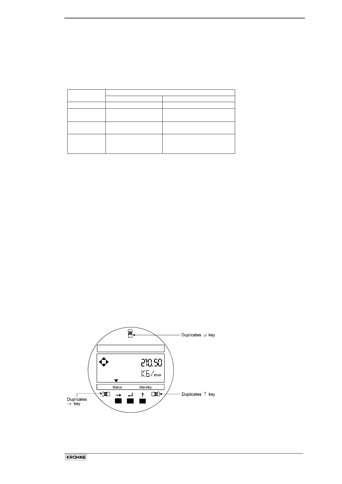
3.4 Programming the converter with a bar magnet
• The converter can be programmed by means of the magnetic sensors mounted on the faceplate
without removing the front lid.
• To do this, a bar magnet (standard supply) is used to activate the sensors by holding the magnet close
to the glass window of the housing lid.
• These sensors then duplicate the functions of the push buttons.
KROHNE MFC 50
• This is mandatory in Ex
environments
• Also recommended in
humid environments