4 Description
10 of 24
Controlmatic E.2
4.5 Configuration and function
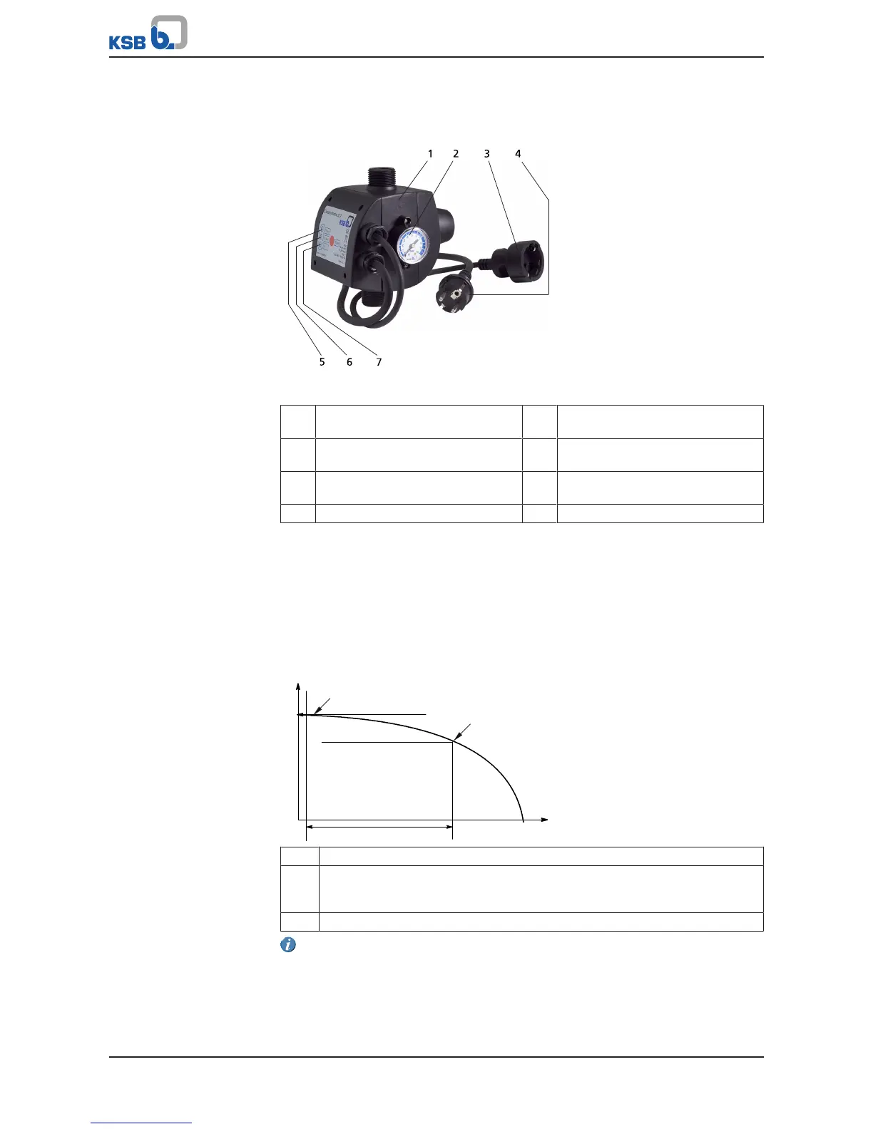
Fig.2: Design of Controlmatic E.2
1 Housing 5 Green signal lamp -
Ready for operation
2 Pressure gauge 6 Yellow signal lamp -
Pump running
3 Plug socket to IEC60884-1 for
connecting the pump
7 Red signal lamp -
Fault or lack of water
4 Power cable with shockproof plug
Function
The pump can be connected via the socket (3) of the automatic control unit. Once
the power cable with shockproof plug (4) has been connected to the power supply,
the automatic control unit is ready for operation. The green signal lamp (5) is lit.
When a shut-off valve in the piping is opened, the system pressure decreases and the
pump is started up. The system pressure is indicated at the pressure gauge (2). The
pump starts to deliver fluid and the yellow signal lamp (6) lights up. When the shut-
off valve has been closed and the flow rate is zero, the pump is stopped after
5seconds.
An integrated check valve prevents the built-up pressure in the discharge line from
decreasing again.
1 Consumer installation closes (zero flow)
2 Consumer installation opens (start-up pressure)
Factory-set to 1.5bar
Can be set at up to 2.5bar
3 Operating range of pump
The automatic control unit cannot be used for pressure boosting. The outlet
pressure is identical to the pump discharge pressure.