ENGLISH
29
1–3 mm
25 mm
2 mm
3-5 mm
1
2
3
4
5
6
7
8
9
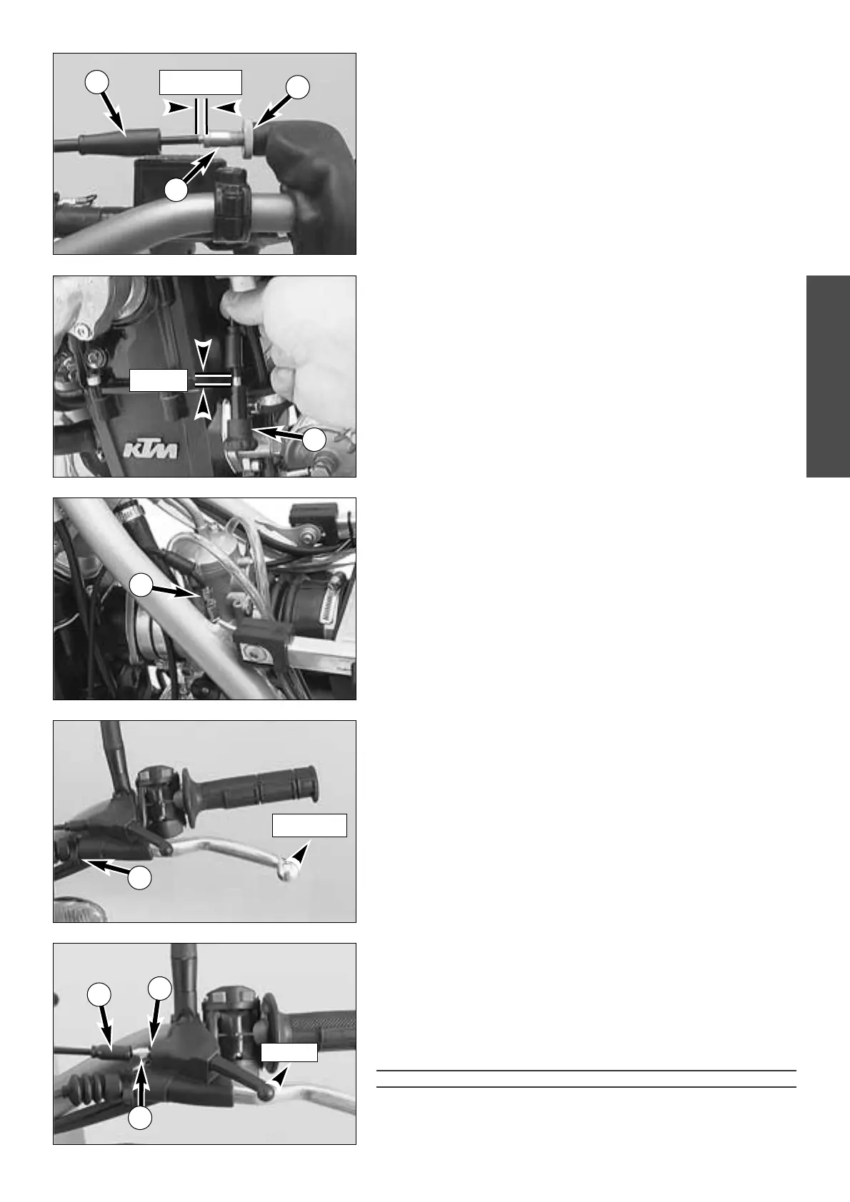
Adjusting the throttle cable
There must always be a 3-5 mm (0,12-0,20 in) play in the throttle cable. To
check this, move back the protective cover
1 on the twist grip. You must
be able to lift the outer covering of the cable 3-5 mm from the adjustment
screw
2, until resistance is felt.
To adjust, loosen the counter nut
3 and turn the adjustment screw
accordingly. With the engine running, turn handlebar, as far as it will go, to
the left and to the right. While doing so, the engine speed must not
change. Finally tighten counter nut and push back protective cover.
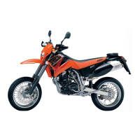
Adjusting the choke cable *
The choke cable must have a play of approximately 2 mm (0,08 in) at all
times. To check the play turn the knob
4 into the initial position. Now it
should be possible to lift the exterior case of the choke cable approximately
2 mm from the supporting surface of the choke knob before the upward
movement is blocked by resistance.
To adjust, remove the seat and the gastank, push the protective cover
upwards, loosen the counter nut and turn the adjustment screw
5
accordingly. Turn the adjustment screw clockwise for more play or
anticlockwise for less play.
Tighten the counter nut, replace the protective cover and mount the
gastank and the seat.
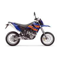
Adjusting the clutch cable
When the engine is cold, the play at the clutch lever should be 1-3 mm
(0,04–0,12 in) (measured at the outer edge).
To adjust the clutch cable turn the adjustment nut
6 accordingly.
Checking the adjustment of the hand decompression release
cable *
To check, set piston at compression, so that the valves are closed. While
doing this, slowly kick the kick starter through its stroke until the clicking
sound (disengaging) of the automatic decompression release can be heard.
Now the deko-lever must be operated 25 mm (1 in) until resistance is felt
(the exhaust valves begin to open). To adjust move back the protective
cover
7, loosen the counter nut 8 and correct the adjustment screw 9
accordingly. Tighten counter nut and push back protective cover.
!
CAUTION
!
I
F THERE IS NO PLAY IN THE DEKO-LEVER, THIS CAN RESULT IN ENGINE DAMAGE.
NOTE:
No adjustment need be made to the automatic decompressor.