8 ERGONOMICS
104
Info
The range of adjustment is limited.
The screw must be screwed in by at least five full turns.
Screwing the push rod into the ball joint adjusts the
foot brake lever downwards.
Screwing the push rod out of the ball joint adjusts the
brake lever upwards.
V01230-10
–
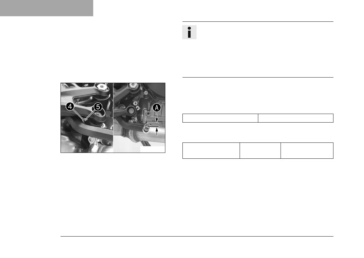
Loosen nut
4
and turn screw
5
correspondingly until the
free travel
A
is present. If necessary, adjust the basic posi-
tion of the foot brake lever.
Guideline
Free travel at foot brake lever 3 … 5 mm (0.12 … 0.2 in)
–
Hold screw
5
and tighten nut
4
.
Guideline
Remaining nuts,
chassis
M6 10 Nm (7.4 lbf ft)

 Loading...