2. Hydraulic control unit use reference chart
In order to use the hydraulics properly, the operator must know the following chart. Though this information may not
be applicable to all types of implements and soil conditions, it is useful for general conditions.
Implement Soil condition
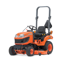
(1) Hydraulic control lever
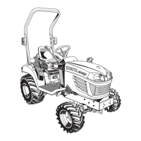
Gauge wheel
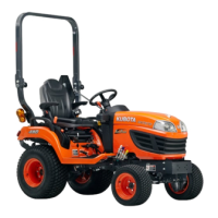
(1) Check chains
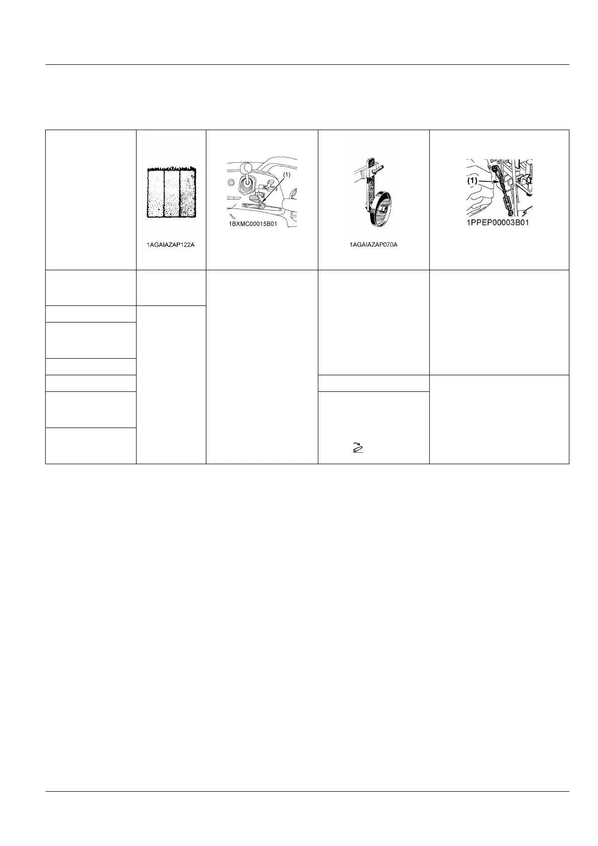
Mouldboard plough
Light soil, medi-
um soil, heavy
soil
Hydraulic control
YES/NO
Loose
Adjust the check chains so that the
implement can move 5 cm to 6 cm
laterally.
The check chains should be tight
enough to prevent excessive imple-
ment movement when implement is
in raised position.
Disc plough
---
Harrower (spike type,
springtooth type, and
disc type)
Sub-soiler
Weeder, ridger YES
Tighten
Earthmove, digger
scraper, and manure
fork rear carrier
YES/NO
For implements with gauge
wheels, set the hydraulic
control lever to the lowered
(down) position all way.
Mower (mid-and rear-
mount type), hayrake,
and tedder
MOWER LIFT LINKAGE SYSTEM HYDRAULIC UNIT