M.5
ELECTRICAL
SYSTEM
68
mm
STROKE
SERIES
WSM,
01
160
(3)
Charging Mechanism
I
I
I
I
01
72F051
nh.
01
72F052
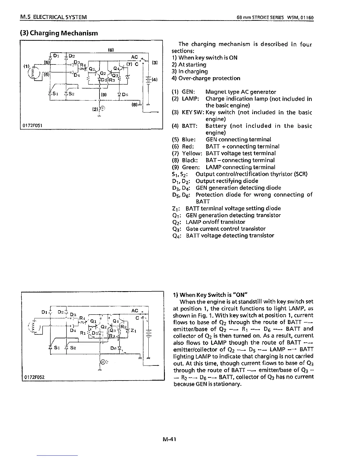
The charging mechanism
is
described
in
four
sections:
1)
When key switch
is
ON
2)
At starting
3)
In
charging
4) Over-charge protection
(1)
GEN: Magnet type AC generator
(2)
LAMP: Charge indication lamp (not included
in
the basic engine)
(3)
KEY
SW:
Key
switch
(not included
in
the basic
engine)
(4) BATT: Battery (not included
in
the basic
engine)
(5)
Blue: GEN connecting terminal
(6)
Red: BATT +connecting terminal
(7)
Yellow: BATT voltage test terminal
(8)
Black: BAT
-
connecting terminal
(9)
Green: LAMP connecting terminal
S1,S2:
Output control/rectification thyristor
(SCR)
D1,
D2:
Output rectifying diode
D3,
Dq:
GEN generation detecting diode
D5, D6:
Protection diode for wrong connecting of
BATT
21;
BATT terminal voltage setting diode
Q1:
GEN generation detecting transistor
Q2:
LAMP on/off transistor
Q3:
Gate current control transistor
Q4:
BATT voltage detecting transistor
1)
When
Key
Switch
is
"ON"
When the engine
is
at standstill
with
key
switch
set
at position
1,
the circuit functions to light LAMP, as
shown
in
Fig.
1.
With key switch at position
1,
current
flows
to
base
of
42
through the route
of
BATT
---
emitter/base
of
Q2
---
R1
---
D6
---
BATT and
collector
of
Q2
is
then turned on. As a result, current
also flows to LAMP though the route
of
BATT
---
emitter/collector of
42
---.
D5
---
LAMP
---
BATT
lighting LAMP to indicate that charging
is
not carried
out. At
this
time, though current
flows
to base of
Q3
through the route of BATT
--+
emitter/base
of
Q3
--
-
Rz
----.
D6
----
BATT, collector of
Q3
has
no current
because GEN
is
stationary.
M-4
1