S.4
FUELSYSTEM
68
mm
STROKE SERIES
WSM,OI
165
I
CO
19F030
I
[2]
INJECTION
PUMP
--
A1
16F
a
3083F065
---
ti:=
6:O
7:-
A078F001
Valve
Seat
Tightness
1.
Set
the
injection nozzle to
a
nozzle
tester.
2.
Raise
the fuel pressure, and keep
at
12.75
MPa
(130 kgfkmz, 1849 psi) for
10
seconds.
3.
If
any fuel leak
is
found, replace the nozzle
piece.
Nofuel
leak
at
12.75
MPa
(130
kgf/crnZ,l849
psi)
Valve
seat
tightness
I
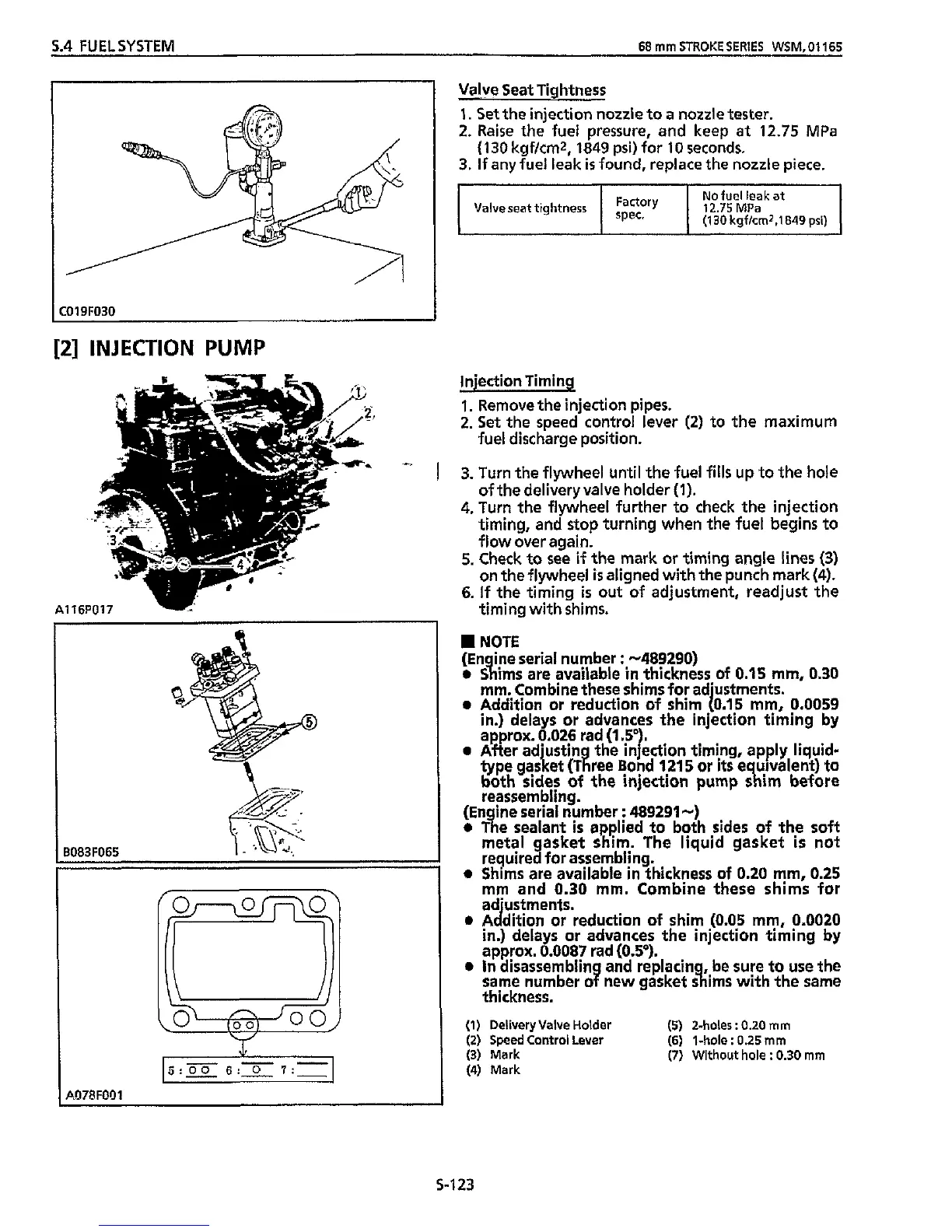
Injection Timing
1. Remove the injection pipes.
2.
Set
the speed control lever
(2)
to the maximum
fuel discharge position.
3.
Turn the flywheel until the fuel
fills
up to the hole
of the delivery
valve
holder
(1).
4.
Turn the flywheel further to check
the
injection
timing, and stop turning when the fuel begins to
flow over again.
5.
Check to see
if
the
mark or timing angle
lines
(3)
on the flywheel
is
aligned with the punch mark
(4).
6.
If
the timing
is
out of adjustment, readjust the
timing with shims.
NOTE
(En ine serial number
:
-489290)
0
S
a
ims
are
available
in
thickness of
0.15
mm,
0.30
mm. Combine these shimsfor ad’ustments.
0
Addition or reduction of shim
10.15
mm,
0.0059
in.) delays or advances the injection timing by
approx.
0.026
rad
(1.59.
0
After ad’ustin the injection timing, apply liquid-
both sides of the injection pump
s
im before
reassembling.
metal gasket shim. The liquid gasket
is
not
required for assembling.
0
Shims are available in thickness
of
0.20
mm,
0.25
mm and
0.30
mm. Combine these shims for
ad’ustments.
in.) delays or advances the injection timing by
approx.
0.0087
rad
(0.5’).
0
in disassemblin and replacin
be
sure to use the
thickness.
s,
type gas
((91
et
(T
ree Bond
1215
or
its
e
urvalent) to
e
T
a
e
sealant
is
applied to both sides of the soft
0
A
d
dition or reduction of shim
(0.05
mm,
0.0020
same number
o
0
new gasket 3ims with the same
(En ine serial number
:
489291~)
(1)
Delivery
Valve
Holder
(5)
2-holes
:
0.20
mm
(2)
Speed
Control
Lever
(6)
l-hole
:
0.25
mm
(3)
Mark (7)
Without
hole
:
0.30
mm
(4) Mark
S-123