5.4
FUEL
SYSTEM
68
mm
STROKE
SERIES
WSM,
01
160
Pressure falling time
A1
16P01
(1)
Speed Control Lever
:zybte
5
seconds
Delivery Valve Fuel Tightness
1.
Remove the injection pipes and injection nozzles.
2. Install the pressure tester (see page 5-55) to the
injection pump.
3. Set the speed control lever
(1)
to the maximum
fuel discharge position.
4.
Turn the flywheel counterclockwise to raise the
fuel pressure to 14.71 MPa (150 kgfkmz, 2133 psi).
5. Set the plunger
of
the injection pump at the
bottom dead center to reduce the delivery
chamber pressure to zero.
6.
Measure the falling time of the fuel pressure from
14.71 to 13.73 MPa (from 150 to 140 kgfkmz, from
2133 to 1991
psi).
7.
If
the measurement
is
less than the allowable limit,
replace the delivery valve or injection pump
assembly.
Fuel overflow pipe
nut
~~~~~z&!$~
14.5 to
18.1
ft-lbs
DISASSEMBLING AND ASSEMBLING
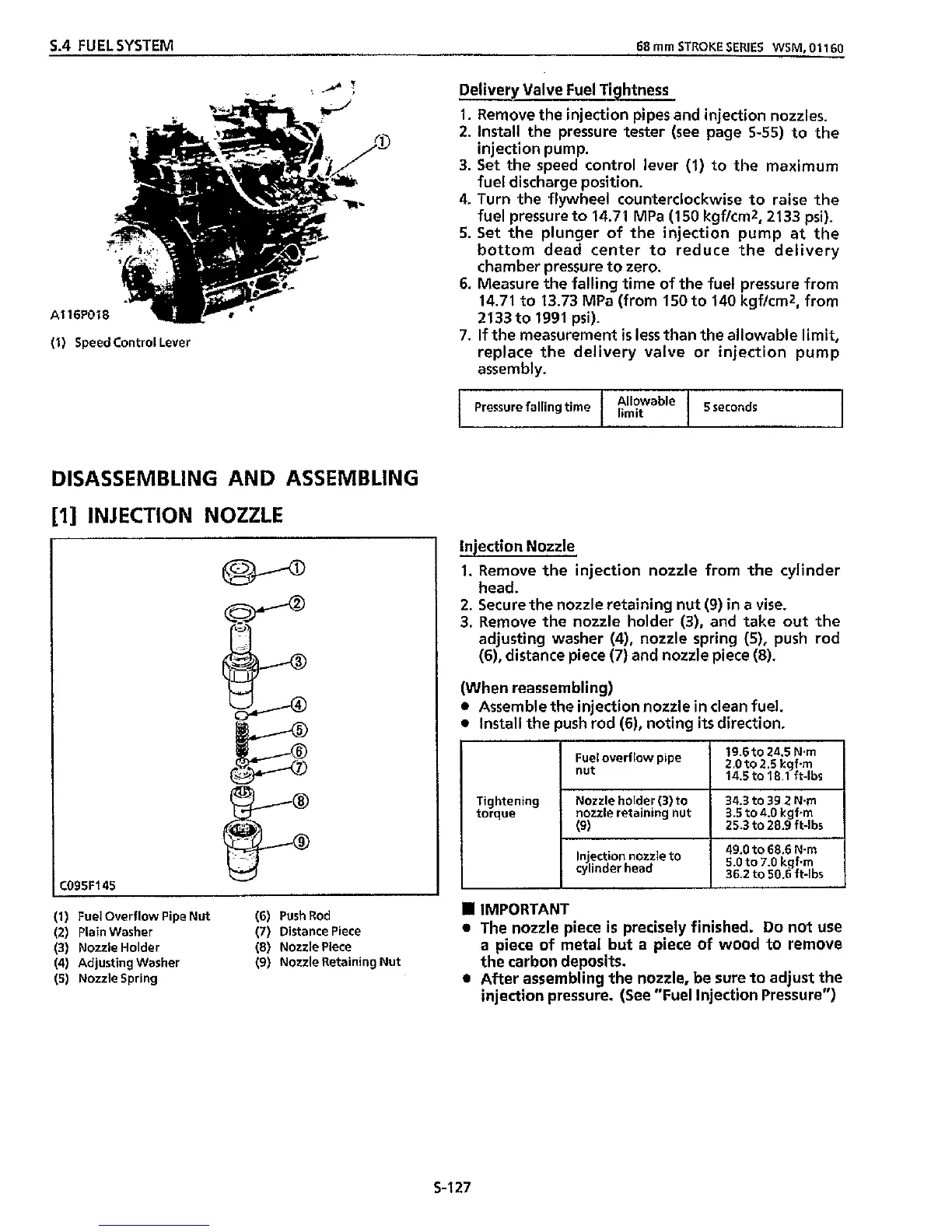
[I]
INJECTION NOZZLE
Nozzle holder
(3)
to
nozzle retaining nut
(9)
C095F
34.3 to
39.2
Nm
3.5 to
4.0
kgfm
25.3
to
28.9
ft-lbs
45
(1)
Fuel Overflow Pipe Nut
(6)
PushRod
(2) Plain Washer
(7)
Distance Piece
(3) Nozzle Holder
(4)
Adjusting Washer
(5) Nozzle Spring
(8)
Nozzle Piece
(9)
Nozzle Retaining Nut
Injection Nozzle
1. Remove the injection nozzle from the cylinder
2. Secure the nozzle retaining nut (9)
in
a vise.
3.
Remove the nozzle holder (3), and take out the
adjusting washer
(4),
nozzle spring (5),
push
rod
(6), distance piece
(7)
and nozzle piece
(8).
(When reassembling)
0
Assemble the injection nozzle
in
clean fuel.
0
Install the push rod
(6),
noting
its
direction.
head.
Tightening
torque
49.0
to
68.6
Nm
5.0
to
7.0
kgf.,,,
Injection nozzle to
cylinder head
I
36.2 to 50.6 ft-lbs
IMPORTANT
0
The nozzle piece
is
precisely
finished.
Do
not use
a
piece
of
metal
but
a
piece
of
wood to remove
the carbon deposits.
0
After assembling the nozzle, be sure to adjust the
injection pressure. (See "Fuel Injection Pressure")
S-127