S.l
ENGINE
BODY
68 mm
STROKE
SERIES
WSM,
01
16A
[4]
TIMING GEAR AND CAMSHAFT
2;
..'
~
A116P012
-
-a-
-.
%+
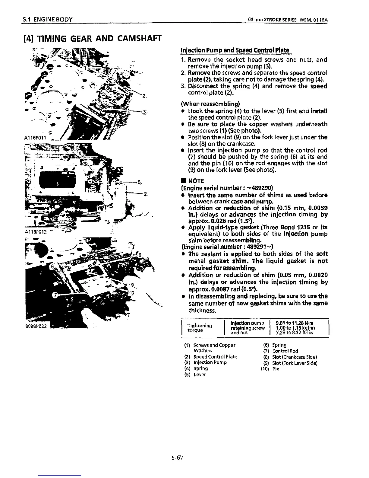
injection Pump and Speed Control
Plate
1.
Remove the socket head screws and nuts, and
remove the injection pump
(3).
2.
Remove the screws and separate the speed control
plate
(2),
taking care not to damage the spring
(4).
3.
Disconnect
the
spring
(4)
and remove the speed
control plate
(2).
(When reassembling)
0
Hook
the spring
(4)
to the
lever
(5)
first and install
the speed control plate
(2).
0
Be sure to place the copper washers underneath
two
screws
(1)
(See photo).
Position the slot
(9)
on the fork lever just under the
slot
(8)
on the crankcase.
Insert the injection pump
so
that the control rod
(7)
should be pushed by the spring
(6)
at
its
end
and the pin
(IO)
on the rod engages with the
slot
(9)
on the fork lever
(See
photo).
W
NOTE
(Engine serial number
:
-489290)
0
insert the same number of shims
as
used before
between crank
case
and pump.
0
Addition or reduction of shim
(0.15
mm,
0.0059
in,) delays or advances the injection timing by
approx.
0.026
rad
(1
So).
0
Apply liquid-type gasket (Three Bond
1215
or
its
equivalent) to both sides of the injection pump
shim before reassembling.
(Engine serial number
:
489291-)
0
The sealant
is
applied to both sides of the soft
metal gasket shim. The liquid gasket
is
not
required for assembling.
0
Addition or reduction of shim
(0.05
mm,
0.0020
in,)
delays or advances
the
injection timing by
approx.
0.0087
rad
(0.5').
0
In disassembling and replacing, be sure to use the
same number of
new
gasket shims with the same
thickness.
I
Injection pump
retaining screw
9.81 to 11.28
N.m
1
.OO
to 1.1
5
kgfem
I
and nut
I
7.23 to 8.32
ft-lbs
Tightening
torque
(1)
Screws and Copper (6) Spring
(2)
Speed Control Plate
(8)
Slot (Crankcase Side)
(3) Injection Pump
(9)
Slot (Fork Lever Side)
(4) Spring
(IO)
Pin
(5)
Lever
Washers (7) Control Rod
5-67