5
BRUBBER PLATES INSTALLATION
[RCK60R]
See "PREVENTING GRASS CLIPPINGS AND DUST
FROM SCATTERING" in the operator's manual
"OPERATING THE MOWER" section.
BINSTALLATION OF UPPER ROPS
1. Install the upper frame with two pin set
assy, locking nuts, and bolts.
A The knob bolts assembled to the upper frame must be
facing the front side of the unit. The locking nuts and
the loop pin of the pin set assy must be inside.
Tightening torque of the bolt and nut should be from 50
to 60N-m (29.5 to 44.3 lbf-ft).
A The tightening order is important to prevent the ROPS
from tilting.
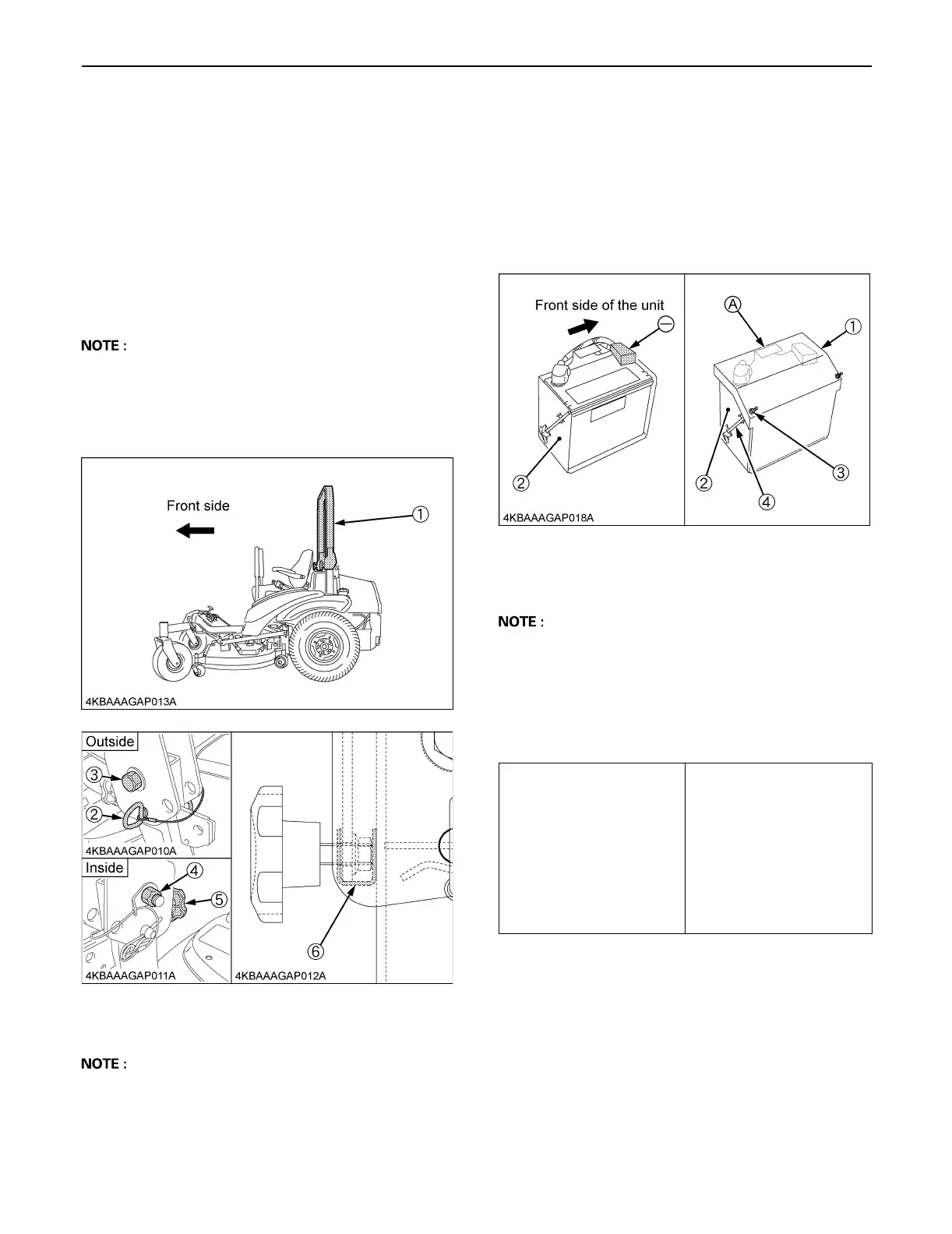
BCONNECT BATTERY'S CABLE
1. Connecting the battery's negative cable
(1) Connect the cable to the battery's negative
terminal. Check the battery and recharge it if
necessary.
(2) Install the battery cover on the base battery with
rod and nut.
A Make sure the part (A) is under the battery cover. Do
not damage the main wire harness.
BESTIMATED ASSEMBLY TIME
Refer to the following table for the estimated assembly
time to open the crate and assemble the machine.
Assembly times on the table are just reference under the
average conditions with following assumption.
1. Assembly by one worker.
2. Following tools and equipment are prepared.
(1) Chain hoist or Crane
(2) Impact wrench
Ratchet wrench
Torque wrench
Socket wrench
and other required tools.
(1) Upper ROPS
(2) Pin set assy
(3) Bolt
(4) Locking nut
(5) Knob bolt
(6) Bracket
(1) Battery cover
(2) Base battery
(3) Nut
(4) Rod
(-): Negative terminal
ZD321N - 54
ZD321 - 60
ZD323 - 60
ZD326S - 60
ZD326P - 60
ZD326RP - 60
ZD331P - 60
ZD331RP - 60
ZD331LP - 72
0 : 04
 Loading...