21 44
EN
1
2
3
4
5
6
8
9
9
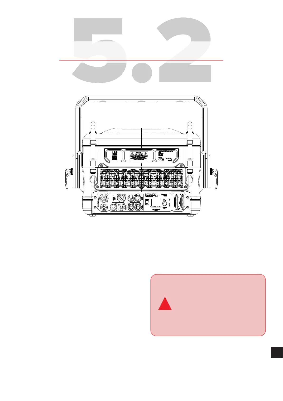
1. Mains power INPUT/OUTPUT. Use supplied Neutrik
powerCON TRUE1 power cable toconnect the laser system
to mains power supply using the INPUT connector. The
OUTPUT connector isused todaisy chain power between
multiple laser systems for quick and easy installation. The
powerCON TRUE1 isaconnector with breaking capacity
(CBC), i.e. itcan beconnected ordisconnected under load
orlive.
2. E-STOP Remote connector, Interlock status indicator
and User Interlock. Inorder touse the laser system, the
Interlock must beclosed circuit. This isdone byconnecting
the Emergency STOP Remote tothe XLR REMOTE INPUT
socket on the projector using the supplied cable. The
US version of the Emergency STOP must also have the
Remote Interlock Bypass inserted into it.
!
The E-STOP Remote is an integral
part of the laser projector. It is there
for the safety of the public as well
as the operator. In most countries
it is required by law to have a fully
working Emergency STOP in place for
every laser system used. Modifying
orusing anything other than the E-STOP
Remote provided, inthe manner itwas
intended, may invalidate your laser
projector’svariance.
The Remote Interlock Bypass may be replaced by the
user’s own interlock system using a switch or dry relay
closure toconnect pins 1and 2. With pins 1 and 2 shorted,
Laser Emission is possible, provided all other interlocks are
closed circuit. With pins 1 and 2 open, NOLaser Emission
ispossible.
The Interlock status indicator START (2) goes o and status
indicator READY (2) lights upwhen the Interlock isclosed
circuit and the Interlock key isinthe ONposition. All above
must bedone correctly toallow laser emission from the
system.