24 41
EN
[ 30 ]
!
Although KVANT uses the latest
technology to protect all the critical
components inside this laser system
against Electrostatic Discharge, the
semiconductor laser diodes within
this system are extremely vulnerable
to it. This is due to some of the
electronic components being exposed
when the top cover is taken o.
If you decide to proceed with the
Beam Alignment process yourself,
it is absolutely essential that all the
common ESD protection rules are
strictly followed. We don’t accept
any responsibility for Electrostatic
Discharge damages to laser diodes
caused bycustomer.
1. Unscrew 14 silver bolts that hold down the top cover
– they are spring loaded and will pop-up once loose.
2. Slowly remove the cover – detach the GND wire that
is attached to the top cover from the inside of the
system! Todetach the wire gently pull itout from the
connector.
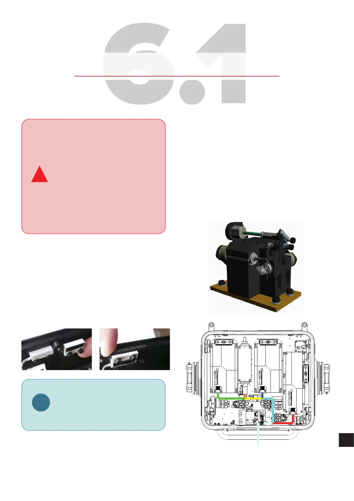
3. Removal of the cover will show the two internal
defeatable magnetic interlocks. You must flip over the
right side ofthe magnetic interlock until ittouches the
other side. You will beable toread the warning label
“Interlock Defeated”.
i
In the defeated position the label
“INTERLOCK DEFEATED” becomes
visible as shown in the image. Placing
the magnetic interlock in the defeated
position raises the interlock higher than
the edge of the housing which will not
allow the cover tobeinstalled.
4. Power upthe system asnormal.
5. Firstly, itisnecessary toalign acolour with the most
direct beam path between the laser module output
and the scanning system in such way so it hits the
exact centre of the bottom scanning mirror – in this
case it can be the blue or red laser beam. We will
choose blue beam towork with first.
6. Create ablue beam eect (point) and check visually
whether the blue beam hits the exact centre of the
bottom scanning mirror. If not, use dichroic mounts
DF2 to adjust the beam path accordingly (diagram
below). To adjust the dichroic mount use the two
adjustment knobs – each works for one axis.
 Loading...