This document describes the Kverneland Group's EC Remote and Flowmate Control (FMC-R) systems, including their components, connections, software information, and testing procedures.
System Overview EC Remote Control
The EC system is a non-regulating system designed for sprayers. It consists of a control box in the tractor that communicates directly with the sprayer's functions via a splitter board.
EC Remote Control Box
The control box features an On/Off LED, water function switches, and hydraulic switches. It supports up to 7 sections and 2 border nozzles.
- Hydraulic Functions: It operates a pre-select system where the operator selects a function and executes it with the tractor's hydraulics. It's available for HPT and HOSA booms and includes an LED for the locking pendulum system.
EC Connections
The system uses a PCB (Pcb_io_20) for connections. The PCB has clearly labeled terminals for various functions, including sections (1-4), pressure, slope correction, agitator, boom lift, folding, and locking cylinder sensors. Specific cable numbers are assigned to positions within the connector for organized wiring.
Elements of Flowmate Control FMC-R
The FMC-R system is a more advanced control system for sprayers, offering greater functionality and expandability.
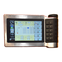
Control Box
- Front Side: The front panel includes selection touch keys for pressure adjustment (P+/P-), spraying (On/Off), return agitator (On/Off), sections (up to 9 sections + 2 border nozzles On/Off), and hydraulics (pre-selection, activate/inactivate, oil circulation system Up/in, Neutral, Down/out). A "Home switch" is also present.
- Rear Side: The rear features a main switch (I=On, 0=Off, II=No function) and connections for the CAN cable (from the splitterbox), speed cable, and speed adaptor.
- Controlbox Inside: The internal wiring shows connections for the display cable, backlight cable, buzzer cable, and a keyboard connector. It also details connections for RADAR, WHEEL, ON, C+, 0V, C-, and 12V, along with a cable to connect the hydraulic switches PCB. Older versions (till 2005) have a specific connector for other PCBs.
Standard Splitterbox Connections
The splitterbox acts as a central hub for various connections.
- Power & Battery Cable: This cable provides electrical power to the system. It connects to a 12V plug on the tractor or a special battery cable. Brown is +12V, Blue is 0V. Connectors should be clean and undamaged.
- CAN Cable: Connects the FMC control box to the splitterbox and the rest of the machine. It uses a black connector plug with specific color-coded contacts for Brown (Cut away), Red (Cut away), Orange (On), Yellow (C+), Green (Ground), Blue (C-), and Black (12V).
- ISO Connection Cable (Splitterbox & SHC-box): Provides power and communication to the Section & Hydraulics PCB. Thick red & black wires (6mm²) supply power for hydraulic valves and section motors. Thin red & black wires (2.5mm²) power the PCB itself. Green & yellow wires are for data communication (CAN+/CAN-).
The SHC Box receives input from various sensors.
- Flow Sensor/Flow Meter: Measures the amount of spraying liquid. Located between the pressure regulator and section valves. Two models exist (<2014 and >2015) with different sizes and flow ranges. Connection: Brown (+12V), White (signal), Green (-).
- Checking Flow Signal: Can be checked on screen 14. The wheel inside the flowmeter should turn easily. If stuck, replace the flow meter or bearings.
- Slope Correction Sensor (90°, black): Measures the angle of the middle frame for position indication and auto-center. Available in 5V and 12V versions. 12V sensors have a visible PCB and part number on a sticker. 5V sensors do not.
- Checking Signal: Can be checked on main screen 1. The indicator line should move when the boom moves. If the locking LED is on, slope correction is blocked.
- Connections: 12V sensor: Brown (+12V to test LED port), Blue (GRND to test LED port), Black (signal to ANA2 port). 5V sensor: Brown (+5V to ANA2 port), Blue (GRND to ANA2 port), Black (signal to ANA2 port).
- Wheel (Speed) Sensor: Provides driving speed for automatic spray quantity regulation. For trailed machines, it connects to the SHC print. Mounted sprayers use a speed sensor with a connector at the control box's backside.
- Connections: Speed sensor: Brown (+12V), Black (signal), Blue (-). Speed sensor with connector: Pin 2 (Signal), Pin 5 (-0V), Pin 7 (+12V). Note: Pin 7 has a ground symbol but is +12V.
- Checking Signal: For trailed sprayers, check screen 11. For mounted sprayers, check screen 11. The green LED on the sensor should burn when metal is in front and be off otherwise.
- Locking Sensor: Indicates if the boom is locked and ready for folding. A red LED on the FMC control box indicates locking, blocking slope correction.
- Checking Signal: Reacts to a magnetic field, not metal. Check with a magnet. LED should burn without a magnet and go out with one.
- Connections: Brown (+), White (signal).
- Pressure Sensor: Used in some semi-continue systems instead of a flow meter. Connects to SHC-PCB at ANA 1. The locking LED connects to DIG 2 (flow sensor connection).
- Attention: Check jumper position on the PCB (5V or 12V "Huba").
- Connections: Brown (+12V), Black (signal), Blue (-).
SHC Box: Output Connections
The SHC Box controls various outputs.
- Pressure Regulator: Controls pressure. Connected to specific outputs on the SHC PCB.
- Connections: Pin 1 (Brown: Positive +), Pin 2 (Green/Yellow: Signal), Pin 3 (No function), Ground (Blue: Negative -). The green/yellow wire must be cut off for the pressure regulator cable.
- Position and Connections of Section Cables: Sections are connected to specific outputs (OUT 2, OUT 3, OUT 4, OUT 5, etc.).
- Connections: Brown (+), White (-), Green (S - signal). The signal switches to ground.
- Adding Border Nozzle: Border nozzles take up two functions of the SHC card.
- Connections: To let the regulator work correctly, Brown is + and Blue is -. Border nozzle Right connects to BR. Border nozzle Left connects to BL.
- Position of Hydraulic Cables: Examples show different configurations for hydraulic functions (out 9-18) and oil circulation.
- Warning: Outputs must be configured correctly in software. Oil circulation may only work in one direction if configured incorrectly.
- Connection of Hydraulic Cables: All systems connected to the SHC card switch the signal to ground. Oil circulation is connected to specific outputs.
- Connection Cables for Hydraulic Valve: Connects hydraulic valves to the SHC PCB.
- Connections: Brown (+12V), Blue (signal).
- Connection Cable Oil Circulation Valve: Has two functions: opening/closing and changing direction of oil flow. Connected to the two slots after the last hydraulic function on the SHC PCB. Brown to continuous PLUS, other two signal cables to empty SIGNAL slots. Diodes prevent shortcuts.
- Connections: Brown (+12V), Black (Signal 1), Blue (Signal 2).
- Total Overview SHC Hydraulic/Section: Provides a comprehensive diagram of all SHC hydraulic and section connections, including jumper positions for pressure sensor and ASV.
Connections for 2 SHC - Boxes
For sprayers with more than 18 output functions, an extra SHC box and splitterbox are used. Water/section and hydraulic functions are separated.
- Extra Splitterbox for 2 SHC boxes: Connects the two SHC boxes. Features POWERtest LED.
- 2 SHC boxes: hydraulics: Diagram shows connections for hydraulic functions.
- 2 SHC Boxes: water/sections: Diagram shows connections for water and section functions.
Connections Automatic Steering System
The optional auto steering system uses a Mini I/O module or STC (Steering Controller).
- Splitterbox with Steering System: The splitterbox PCB has three connection slots for options. Wire plan for Mini I/O power & valve cable: Wires 1+2 to CAN Power Plus (+), Wires 3+4 to CAN Power Minus (-), Wire 5 to CAN High, Yellow/green wire to CAN Low.
- Power Cable Steering System Mini I/O: Connects steering valves (Left/Right) and power/communication to the Mini I/O.
- Sensor Cable Mini I/O: The Mini I/O works with three sensors: Boom in sensor (12V), 180 degree sensor (5V or 12V), 180 degree sensor (5V or 12V). Each cable has a sensor name sticker.
- Warning: Connect the right sensor to the right cable due to voltage differences.
- 180 Degree Sensor: Two types: 5V (light blue, pre-11/2014) and 12V (dark blue, post-11/2014). Mini I/O units are specific to 5V or 12V sensors, indicated by a sticker.
- Mini I/O Inside: Internal view of the Mini I/O, showing placed and not placed components.
ASV (Automatic Suction Valve)
The ASV system integrates with the FMC control box, splitterbox, and SHC box.
- ASV System Overview: Shows the ASV connected to the splitterbox and SHC box, with fuse locations.
- ASV Inside: Internal view of the ASV pilotbox, showing jumper settings for ASV MOUNTED and ASV TRAILED.
- Important: Check jumper positions (Mounted: placed, Trailed: removed).
- ASV Inside (Sensors): The ASV pilotbox has two connection places for 180 degree sensors (5V and 12V). Ensure the correct sensor is connected.
- ASV Cables: The potential meter for the level indicator is connected by a separate cable.
- Suction Valve Motor: The ASV suction valve has different valve positions due to switch plate and micro switch positions. Electronic diagram and connections are consistent.
- Trailed machines. Ikarus S and Ixtrack: Shows the main tank, clean water tank, and suction hose connector. No function is shown in the bottom left.
- Mounted Ixter: Shows the main tank, clean water tank, suction hose connector, and drain function. When drain is selected, the valve is between the main tank and the drain.
System Testing Possibilities
Controlbox and Switches
- Testdisplay: Shows key and switch states.
- Switch Test: Each 1, 0, - position corresponds to switch position (up, middle, down).
- Push Button Test: Shows key numbers (0-5) when buttons are pressed.
- Sensor - Test: R=1 (radar sensor), W=1 (wheel sensor).
- Buzzer Test: Press OK, buzzer sounds.
- Display Test: Press OK, display tests.
- LED - Test: Press OK, LED tests (locking cylinder).
SHC-box
- Standard: Green and red test LEDs burn. If only a single cable is connected to "S" at the test position, green and red LEDs burn.
- + (plus 12V) Test: Connect a single cable to "S" at test position and to "+" at another position, red LED burns.
- - (minus) Test: Connect a single cable to "S" at test position and to "-" at another position, green LED burns.
- "S" Signal Test: Connect a single cable to "S" of test position and "S" of another position, activate the corresponding switch. Green LED burns when activated (signal is based on minus).
Cable and Sensor Test
- Example Hydraulic Cable: Disconnect cable, bridge positions 1 and 2 of the plug. Red LED burns because + (plus) is connected to the signal cable.
- Speed Sensor (Machine) and Flow Sensor Test: Diagrams show how to test these sensors.
- Locking Sensor Test: Diagrams show how to test the locking sensor with a magnet.
This section details various screens and their parameters, with explanations for each. Users are advised to only refer to the parameter list for their specific model.
- Main Screen: Displays sections (on/off), auto/man mode, remaining distance, spraying target, middle frame position, actual l/ha, main valve on/off, speed, agitator on/off.
- Quantity in Tank Screen: Shows quantity in tank, ltr. sprayed, ha. sprayed, actual flow, droplet size, nozzle choice.
- Priming/Rinsing Booms Screen: For priming and rinsing booms.
- Field Registration Screen: For field registration.
- Setup Functions Screen: Accessed by pressing OK.
- Alarm Signal Screen: For droplet, high/low pressure alarms. Tank min alarm is always active.
- Contrast Adjustment Screen: Adjusts screen contrast.
- Buzzer Loudness Screen: Adjusts buzzer volume.
- Normal Tank Volume Screen: Sets normal tank volume.
- Tank Low Alarm Screen: Sets alarm for low tank volume.
- Slope Correction Calibration Screen: Calibrates slope correction.
- L/ha Step Change Screen: Sets step for L/ha changes.
- Information Screen: Displays area memory and volume memory.
- Incoming Speed Signal Source Screen: Selects tractor, radar, machine, or Starguide 2.
- Calibrate Speed Sensor Screen: Calibrates speed sensor (impulses/meter, distance).
- Impulses Radar Sensor Screen: Displays impulses for radar sensor (only when radar is selected).
- Pressure/Flow Information Screen: Displays current bar, l/min, min/max bar.
- Flow Meter Adjustment Screen: Quick adjust for flow meter (e.g., liquid fertilizers).
- Sensor Choice Screen: Choose flow sensor or pressure sensor.
- Voltage in System Screen: Displays voltage for control box (BC) and SHC boxes (Imp).
- Time and Date Screen: Sets time and date.
- Software Version Controlbox Screen: Displays control box software version.
- Software Version SHC Box Screen: Displays SHC box software versions (water/hydraulics).
- Software Information Mini I/O Screen: Displays Mini I/O software information (Steering controller).
- Calibrate Sensor Screen: Calibrates front and rear sensors.
- Steering System Parameters Screen: Displays DZ, axle gnl/gnr, Ikarus S gnl/gnr, Ixtrack gnl/gnr.
- Calibrate Limit Screen: Calibrates steering limit (AD = Axle, Drawbar).
- Software Version ASV Pilotbox Screen: Displays ASV pilotbox software version.
- Machine Hydraulic Configuration Screen: Sets number of sections, main valve yes/no, border nozzle yes/no.
- Oil Circulation Yes/No Screen: Sets oil circulation.
- ID Number PCB Screen: Displays ID numbers for water and hydraulic PCBs.
- Wheel Steering/Drawbar Steering Screen: Sets maximum steering angle.
- Sensor Output Information Screen: Displays sensor outputs (rear, front, boom in sensor).
- Type of Section Valve Screen: Sets type of section valve.
- Distance Between Nozzle Screen: Sets distance between nozzles.
- Calibrate Pressure Sensor Screen: Calibrates pressure sensor.
- Regulator Parameters Screen: No reg (dead zone), P zone, Ton (active time), Toff (inactive time).
- Rev D Parameters Screen: Rev D (extra active regulator time), P zone, Ton, Toff.
- Regulator Delay/Flowmeter Input Screen: Regulator delay time, Q low (flowmeter input threshold).
- Filter Values for Sensors Screen: Sp (speed), Fl (flow), PR (pressure sensor), Al (alarm delay time).
- Delay Time Locking LED Screen: Sets delay time for locking LED.
- Total Area of Machine Screen: Displays total area (cannot be reset).
- Hose Length/Diameter Screens: For suction valve/pump, pump to regulator, regulator to section valves, sprayline.
- Section Valve to Sprayline Length Screens: Sets length from section valve to sprayline.
- Setup Functions Exit Screen: Always leave setup functions by the flag to save values.
Special Alarm Screens
- Normal Main Display: Shows standard operating information.
- Tank Level Below Min Alarm: Appears when tank level is below minimum.
- Pressure Too High Alarm: Appears when pressure is too high for nozzle information.
- No Communication to SHC-box Water Alarm: "!S" flashes.
- No Communication to SHC - box Water and Hydraulics Alarm: "IS + IH" flash alternately.
- Spraying Off (All Sections Closed) Alarm: Appears when all sections are closed.
- Steering Potentiometer Out of Range Alarm: Blocks automatic steering.
- No Section with Work Width Adjusted Alarm: Appears when work width is not adjusted.
Calibrate Slope Correction
- Procedure: Put hydraulic hillside correction to central position by pressing switch E. The display (M) should show the central position. If not, re-calibrate in Setting and Service Menu (Screen 8). Press OK to enter input mode, confirm "OK = 0" flashes. Confirm again until two short peeps sound.
- Central Position: Achieved when the lower rectangular tube (13) of the pendulum frame is parallel to the carrying frame (12). Use a water leveler on the boom on a horizontal surface.
Calibrate Speed Sensor (Wheel or Radar)
- Calibrate Wheel Speed: In Screen 12, input impulses per liter for driven distance. The upper value is impulses, lower is measured distance.
- Procedure: Set a measurement distance (e.g., 100m). Press arrow key to start calibration. Drive the distance, press OK. Confirm with OK. Adjust value if needed.
- Tip: If pulses > 1000/100m, reduce distance.
- Note: Calibrate on a field with a half-full spray tank to minimize errors.
- Calibrate Radar Speed: If using a radar sensor or Starguide, calibration is done in Screen 13. Manually enter impulses per meter (basic setting: 130 impulses/meter). For Dicky John I-speed: 93 pulses/meter.
Calibrate Flowmeter
- Procedure: Screen 14 shows flow meter calibration. Input impulses per liter (from flow meter) in Screen 12.
- Gauging Procedure: Fill with clear water, set operating elements to "Spraying". Turn on PTO (540 rpm). Switch all section switches to "On". Central switch "Spraying" to "On". Select Screen 14. Determine nozzle output (at least 5 nozzles) with a measurement vessel. Average and calculate. If calculated l/min doesn't match display, correct and confirm with OK.
- Important Note: PTO speed and pressure regulator must not be altered during the entire sequence.
Calibrate Unknown Nozzle
- Option 1 (Manual Input): Obtain nozzle information from supplier. Choose pressure in the middle of the range (e.g., 4 bar). Fill in data on the screen.
- Option 2 (Manual Measurement):
- Spray on manual mode with 3 bar pressure.
- Measure 5 different nozzles over 1 minute.
- Calculate the average.
- Determine min and max pressure (usually 2-8 bar).
- Fill in the values on the screen.
Calibrating Pressure Sensor
- Procedure: Screen 45 contains calibration. If measured nozzle output doesn't match calculated flow in main screen 2, adjust pressure value in screen 45. Increase if measured is higher, decrease if lower.
- Calibration Steps: Fill with clear water, set to "Spraying". Turn on PTO (540 rpm). All section switches "On". Central switch "Spraying" to "On". Regulator in Manual mode. Measure output of 5 nozzles. Calculate average. Compare measured l/min with calculated l/min in main screen 2.
- Note: Other values in screen 45 should not be changed.
- Procedure: Ensure configuration matches wire connections.
- First line flashes.
- Move active switches up (1), inactive switches down (0).
- Store SW (RP flashing).
- Adjust oil circulation (RP).
- Store RP.
Calibration and Explanation Steering System
- Procedure: Follow steps sequentially for a good track following system.
- Put Wheels and Drawbar Straight: Steer with manual mode to middle. Check power on STC box (Screen 29, 10-13V). If screens 29-32 not shown, check connections and restart.
- Check Parallelogram/Position Steering Sensors: Front sensor: arm and rod make a parallelogram, arm at 90° to drawbar in middle. Rear sensor: position depends on machine. iXtrack/Ikarus: sensor in line with cable, rod in middle of 180° working area.
- Calibrate Center Position Sensors: Go to Screen 30. Middle position is ~450 counts (Explorer steering axle from 2006: ~420 counts). Select 1st value (front sensor), confirm. Select 2nd value, set to 0. Select 3rd value (rear sensor), confirm.
- Set Dead Zones to Default: Go to Screen 31. "Big" dead zone (default 10) for track following. "Small" dead zone (default 4) for middle position. Increase BIG DZ if nervous, decrease if slow. Increase SMALL DZ if nervous around middle, decrease if not exactly back in middle.
- Set GAIN to Default: Go to Screen 31. Gain is reaction between front/rear sensors. Higher gain = less steering reaction, lower gain = more. Default values: Ikarus (+0.05), Phoenix (-0.05) for drawbar; Explorer (+0.70), Phoenix (+0.70) for wheel.
- Set LIMIT: Go to Screen 32. Restricts maximum steering angle for safety. Select value, steer manually to max allowed angle (check both sides), press OK.
- Attention: If LIMIT is 0, steering system won't react. Always set LIMIT.
- AD (Steering Delay): Wheels start turning after this distance. Drawbar AD=0. Wheel AD depends on length/speed. Works with speed sensor on SHC PCB. From FMC V1.12, also works with speed signal directly to controlbox.
- Adjust Hydraulic Steering Speed: Go to Screen 38. Adjust oil flow from tractor (~25 l/min) and restrictor on steering valve block for fine tuning. Check proportional steering values (0V=close, 12V=open) for smooth opening/closing. Centerspeed is opening of steering valve in %.
- Adjust MAN LIMIT: Go to Screen 39. Prevents steering system activation with folded booms. Manual steering allowed till certain angle.
- Adjust GAIN in the Field: Drive in AUTO mode, booms folded out, in a circle. Wheels should follow tractor's rear wheels. If inside track, lower GAIN. If outside, higher GAIN. Adjust GNL/GNR for left/right differences.
- Adjust 2 Dead Zones in the Field: Increase BIG DZ if nervous, decrease if slow. Increase SMALL DZ if steering stays moving in middle, decrease if not complete back in middle.
Operations Screens
- Fill Tank (External Hose): Fills tank via external hose.
- Drain Function: Drains tank (only visible on Ixter sprayer).
- Filling by Sprayer Pump: Fills tank using sprayer pump.
- Clean Water Tank to Main Tank: Pumps clean water to main tank.
- Suction Filter Cleaning: Cleans suction filter.
- Exit: Exits operations screens.
- Additional Information: Drain function visibility depends on machine type parameter (flash tool only). Tank size < 2000L defaults to Ixter, > 2000L defaults to Ikarus S.
Adjustment & Calibration Screens
- Key Volume: Sets volume keys.
- Alarm Volume: Sets alarm signal volume.
- Alarm Level: Sets percentage for alarm activation.
- Fill Step Size: Sets scale for filling.
- Auto Valve: Disconnected (no electronic valve, level indicator only) or Connected (suction valve connected to ASV).
- Language: Selects language (Nederlands, German, French, Englisch).
- Calibration: See next pages for instructions.
- Software Info: Displays ASV software version.
- Exit: Exits screens to main screen.
Testing Screens
- LCD Test: Test screen for mechatronics use.
- Buzzer Test: Tests buzzer.
- Valve Test: Tests valve function (Ikarus S: ensure correct valve position).
- Level Sensor: Displays sensor counts (Level top +/-300, Level down +/-700 for Ixter).
- Flow: Displays flow sensor signal (l/min).
- Exit: Exits screens to main screen.
Calibrating Electronic Level Indicator
- Procedure:
- Calibrate spray flow meters.
- Fill tank with clean water (Normal tank size + 100L for Ixter, + 40L for Ikarus S). Ensure float isn't touching top.
- Go to Calibration screen.
- Press OK, "Start" appears.
- Press OK, "Start Sprayer" pops up.
- Switch off agitation.
- Open main valve on FMC control box.
- Check if liters on ASV screen run.
- Look inside tank, switch off main valve when float touches bottom.
- "Cal. Completed" appears.
- Confirm with OK.
- Extra Added Function: If an error occurs, push the button. Calibration stops, sprayer still sprays. Switch main valve and control box off/on. Previous calibration value is saved.
- Parameter 25 (Tank Level Filter): Adjustable with flashtool. Ixter/Ikarus S default 15. Ixtrack needs to be changed to 2.
- Parameter 26 (Machine Type): Responsible for flow schedule, linked to tank size. 0 = Ixter (<2000L), 1 = Trailed (>2000L).
- Parameter 27 (Reverse Sensor): Adjustable with flashtool. Ixter 0. Ikarus S 1 (sensors work upside down).