27
TracNet H90 Installation Guide
No-Transmit Zones (Optional)
No-Transmit Zones (Optional)
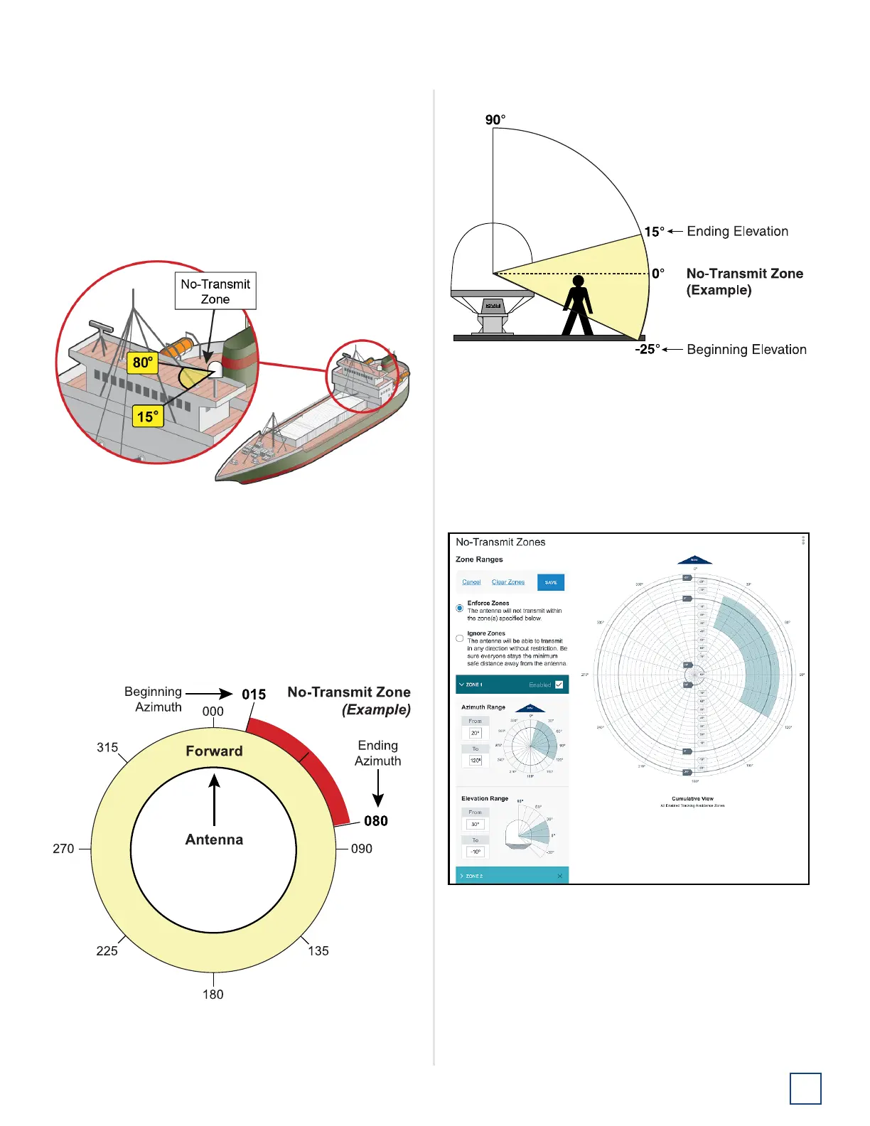
To prevent exposure to RF energy (see page 1 for an
illustration of the hazard area), you can configure up to two
no-transmit zones for areas where crew and/or passengers
frequent. The system will disable the transmitter whenever
the antenna is pointing within one of these zones.
Figure 47: Example of a No-Transmit Zone
Follow these steps to set up a no-transmit zone.
1. Determine the necessary azimuth range for the no-
transmit zone(s). You will need to enter, in clockwise
order, beginning and ending azimuths that define the
outer boundaries of the zone(s) relative to the
antenna’s forward arrow, which should be pointing
toward the bow.
Figure 48: Azimuth Relative to Antenna’s Forward Arrow
2. Determine the necessary elevation range for each no-
transmit zone.
Figure 49: Example of No-Transmit Zone Elevation Range
Note: Each no-transmit zone must span at least 5° in both
azimuth and elevation.
3. At the web interface, select the No-Transmit Zones
page. Then select Edit.
4. Select Enforce Zones.
Figure 50: No-Transmit Zones Page of Web Interface
5. Enter the azimuth and elevation ranges for Zone 1.
6. Enter the azimuth and elevation ranges for Zone 2, if
required.
7. Select Save.
 Loading...

