23
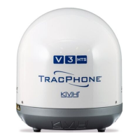
To prevent exposure to RF energy (see the hazard
area illustration on page 1), you can configure up
to two no-transmit zones for areas where crew
and/or passengers frequent (see Figure 40). The
system will disable the transmitter whenever the
antenna is pointing within one of these zones.
Follow these steps to set up a no-transmit zone.
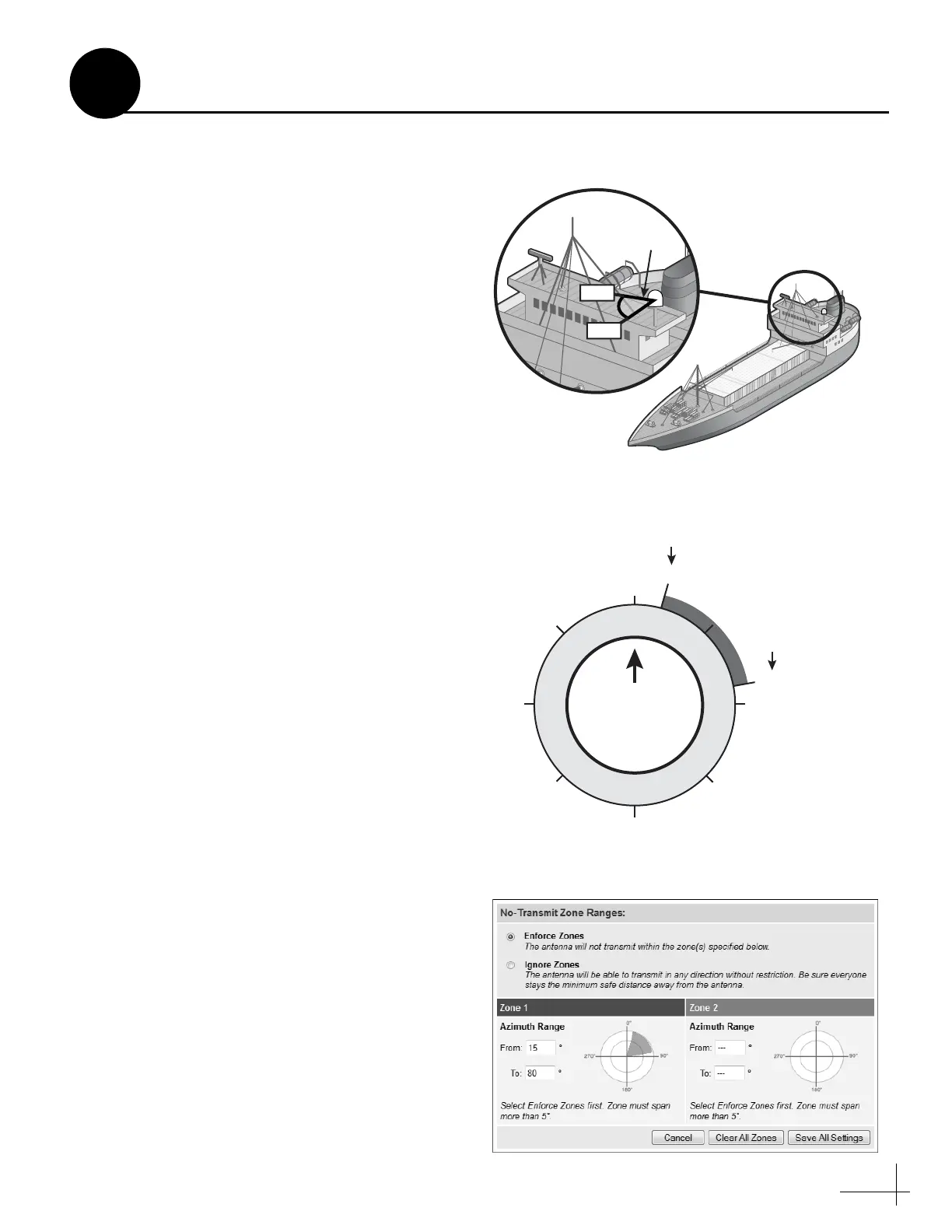
a. Determine the necessary azimuth range for
the no-transmit zone(s). You will need to
enter, in clockwise order, beginning and
ending azimuths that define the outer
boundaries of the zone(s) relative to the
antenna’s forward arrow, which should be
pointing toward the bow (see Figure 41).
NOTE: Each no-transmit zone must span at least 5°.
Therefore, be sure to set the beginning and ending
azimuths at least 5º apart.
b. At the TracPhone V3-HTS web interface, click
the Settings tab. Then click No-Transmit
Zones.
c. Click Edit.
d. Click Enforce Zones (see Figure 42).
e. Enter the azimuth range for Zone 1.
f. Enter the azimuth range for Zone 2, if
required.
g. Click Save All Settings.
h. At the confirmation message, click Save.
Figure 40: Example of a No-Transmit Zone
Antenna
000
180
090270
135
225
315
Forward
015
080
Beginning
Azimuth
Ending
Azimuth
No-Transmit Zone
(Example)
Figure 41: Azimuths Relative to Antenna’s Forward Arrow
Figure 42: No-Transmit Zones Page of Web Interface
Set Up No-Transmit Zones
15
Optional
 Loading...