5
Select the antenna mounting site(s) based on the
guidelines within this section. Guidelines are
organized into the following categories:
• Mounting Surface
• Power/Data Cable Length
•Blockage
• Antenna Orientation
• Radar/High-Power Radio Transmitters
Mounting Surface
• If available, install the antenna on a platform
or pedestal, rather than on a deck. Both
service hatches should be fully accessible for
installation and service.
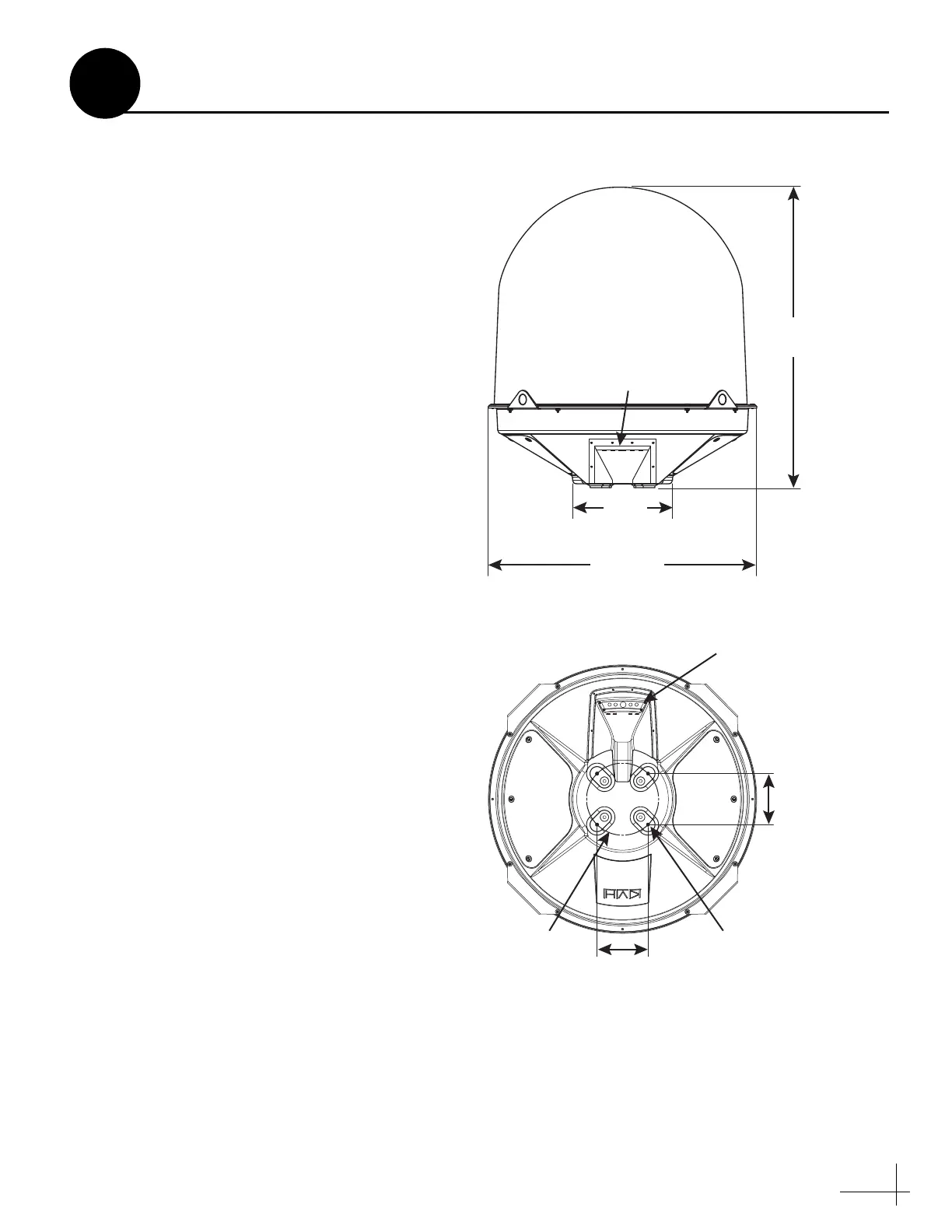
• Make sure the mounting surface is wide
enough to accommodate the antenna’s base
(see Figure 3). Also make sure it is flat, level
(within ±1°), strong enough to support the
antenna’s weight (200 lbs (90 kg)), and rigid
enough to withstand vibration.
• Choose a mounting surface as close as
possible to the intersection of the vessel’s
centerline and midships.
Power/Data Cable Length
If you wish to use the supplied power/data
cable, the antenna must be mounted within 100 ft
(30 m) of its ACU. However, you can order a
longer cable if needed – contact KVH for details.
Plan the Antenna Installation
Figure 3 Antenna Dimensions
13V/22KHz
18V/22KHz
Power/D ata
13V
18V
57.28"
(145.50 cm)
19.01"
(48.29 cm)
ø51.315"
(130.34 cm)
9.744"
(24.75 cm)
9.744"
(24.75 cm)
Mounting Hole
4x ø.63" (1.60 cm)
ø13.780"
(35.00 cm)
Cable Connectors
(cable cover not shown)
Service
Hatch
Service
Hatch
Side View
Bottom View
Cable
Connectors
3

 Loading...


