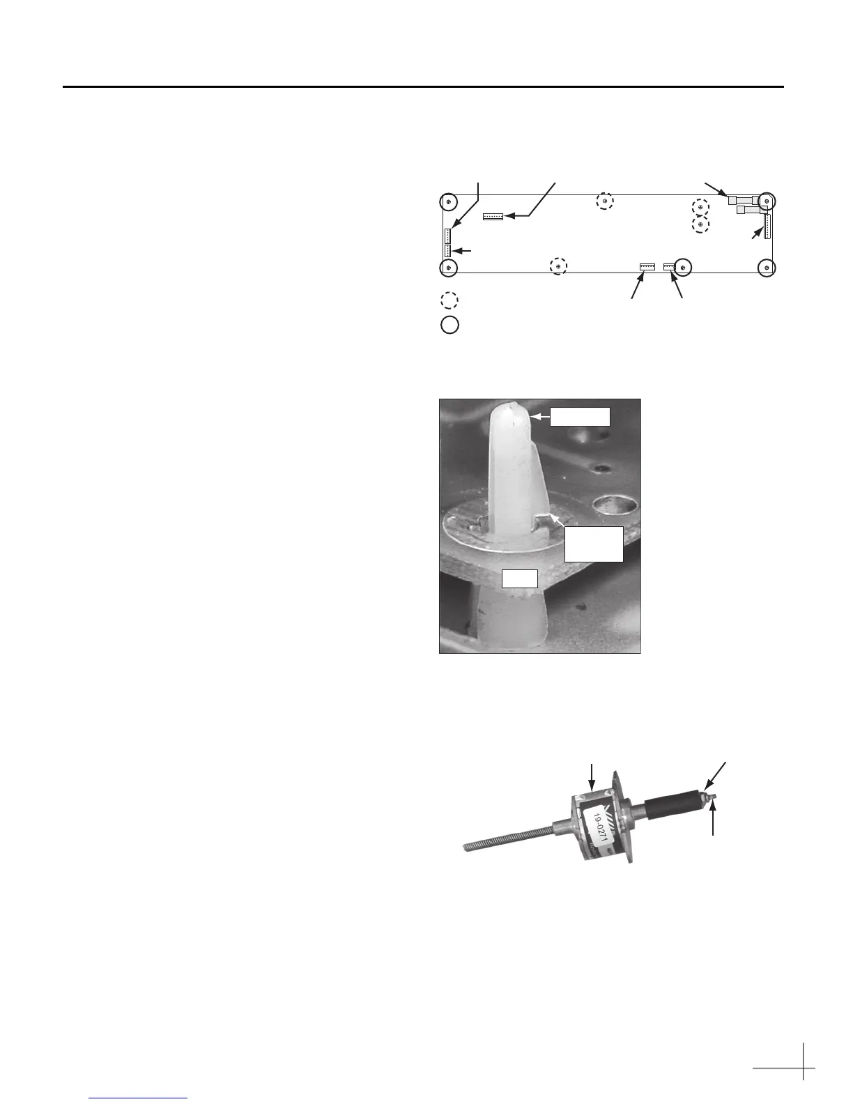
3
h. Remove all cable connectors from the main
PCB (see Figure 4).
i. Remove the four Phillips screws securing the
main PCB to the rotating plate.
j. Using needle-nose pliers, carefully depress
the tab of the standoff located next to the RF
PCB connector on the main PCB (see Figure 4
and Figure 5).
k. Carefully raise the PCB over the tab. Repeat
this procedure for each of the other four
standoffs (see Figure 4).
l. Remove the PCB.
m. Install the replacement main PCB. Ensure the
main PCB is secured by the standoffs, then
using the four screws that you removed in
Step h, secure the main PCB to the rotating
plate (see Figure 4).
n. Reconnect all cable connectors to the main
PCB (see Figure 4).
o. Gently install the main PCB cover, ensuring
no cables are damaged by the edges of the
cover. Then secure the main PCB cover using
the four screws you removed in Step e on
page 2.
p. Secure the elevation motor to the elevation
motor mounting plate using the two screws
you removed in Step 1f on page 2.
q. Apply a small amount of the supplied Loctite
threadlocker to the threads of the elevation
motor shaft, just above the motor shaft nut
(see Figure 6).
r. Extend the elevation motor shaft by rotating
it clockwise, then insert the motor shaft into
the connecting rod (see Figure 2 on page 2).
s. Using an 11/32" open-end wrench, tighten
the elevation motor shaft nut (see Figure 2 on
page 2).
t. Reinstall the radome. Then reconnect power
to the TracVision system.
Figure 4 Main PCB Connectors/Screws/Standoffs
Figure 5 PCB Standoff
Figure 6 Loctite Application (motor shown unmounted for clarity
purposes only)
RF PCB (J9)
Main PCB
Gyro (R5SL
Only) (J5)
Elevation
Motor (J2)
Azimuth
Motor (J1)
Power
Data (J2)
Fuse (x2)
= Screw (x4)
= Standoff (x5)
Limit
Switches (J9)
PCB
Standoff
Standoff
Tab
Nut
Elevation
Motor
Apply Loctite
Here
 Loading...