2
Step 1 - Replace the Main PCB
The following steps explain how to replace the
main PCB.
a. Disconnect power from the TracVision
system and any connected receivers and/or
multiswitch.
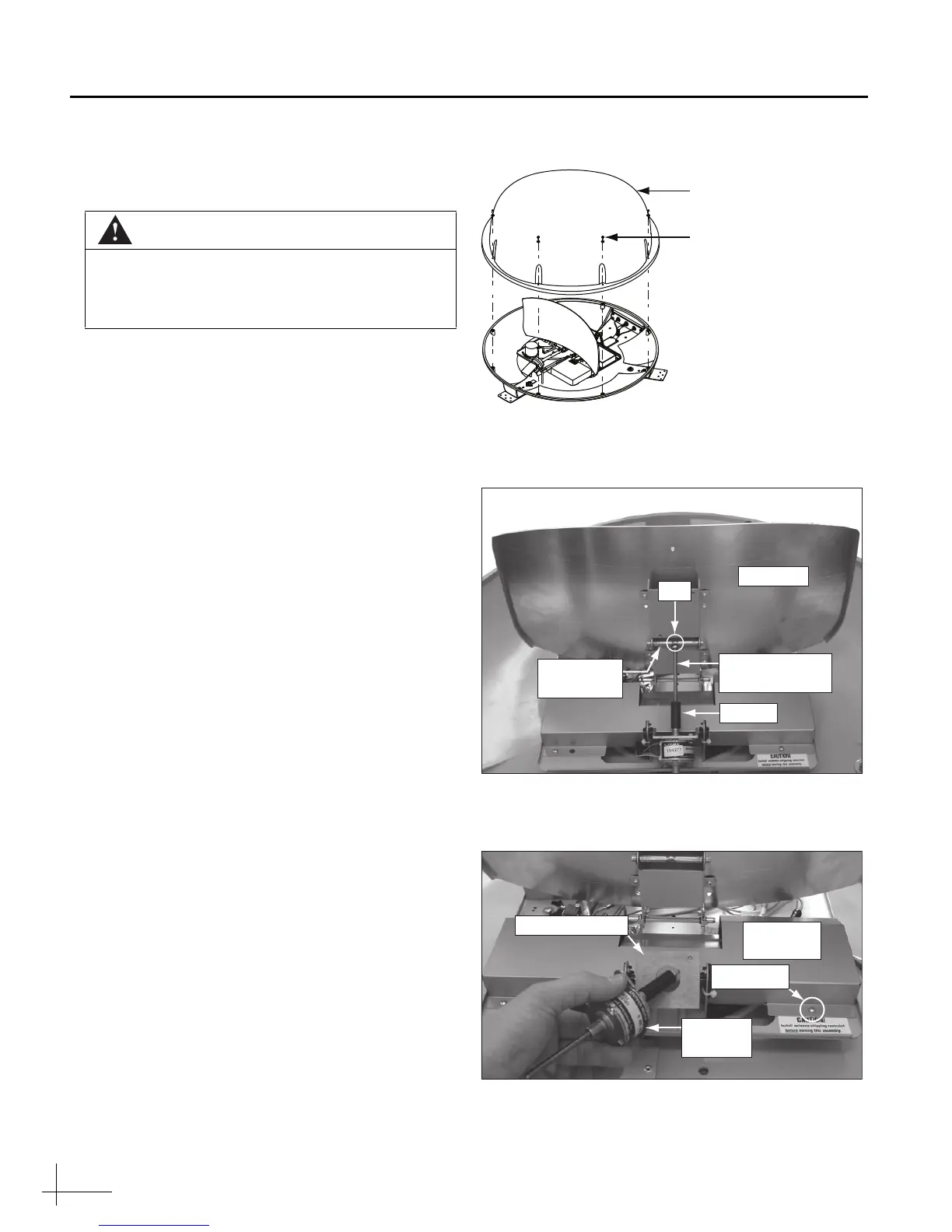
b. Remove the eight screws securing the
radome (see Figure 1). Then remove the
radome and set it aside in a safe place.
c. Using an 11/32" open-end wrench, loosen the
elevation motor shaft nut, but do not remove
it (see Figure 2).
d. Rotate the elevation motor shaft counter-
clockwise until the motor shaft nut is flush
with the spacer.
e. Using a Phillips-head screwdriver, remove
the four screws from the main PCB cover (see
Figure 3).
f. Remove the two Phillips screws securing the
elevation motor to the elevation motor
mounting plate. Then remove the elevation
motor from the mounting plate and set it
aside (see Figure 3).
g. Gently remove the main PCB cover, ensuring
no cables are damaged or pinched by the
edges of the cover.
CAUTION
For your own safety, be sure to disconnect
power from all wired components before
performing this procedure.
Figure 1 Radome Screws
Figure 2 Elevation Motor Shaft Nut
Figure 3 Elevation Motor/Main PCB Screws
Reflector
Elevation Motor
Shaft
Spacer
Nut
Connecting
Rod
Elevation
Motor
Mounting Plate
Main PCB
Cover
Screw (x4)
 Loading...