Do you have a question about the Kwikset 905 and is the answer not in the manual?
Verify the hole in the door is 2-1/8" (54 mm).
Confirm the backset is either 2-3/8" or 2-3/4" (60 or 70 mm).
Measure to confirm the hole in the door edge is 1" (25 mm).
Measure to confirm the door is 1-3/8" or 1-3/4" (35 mm or 45 mm) thick.
Align latch face flush with door edge and secure with screws.
Adjust latch if slotted hole is not centered; rotate face to extend.
Install strike on door frame, ensuring the hole is deep enough.
Route the cable below the latch for exterior assembly connection.
Attach mounting plate to door using appropriate screws for door thickness.
Insert the tailpiece into the slot of the latch mechanism.
Align colored edges of connectors for a tight cable connection.
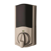
Mount interior assembly and secure with screws.
Load 4 AA batteries into the interior assembly, ensuring correct polarity.
Identify if the latch is left-locking or right-locking.
Press PROG, 12, PROG to set direction if latch bolt goes left.
Press PROG, 56, PROG to set direction if latch bolt goes right.
Steps to add a new 4-8 digit user code.
Extend latch to lock and retract to unlock using the keypad.
Reinstall the terminal cover after programming is complete.
Guide for adding new user codes to the lock.
Instructions for enabling or disabling audible beeps.
Steps to remove an existing user code from the lock.
Procedure to perform a factory reset on the lock.
Use a 9-Volt battery to temporarily power the lock when AA batteries are low.
Replace the terminal cover after accessing battery terminals.
Read all instructions and familiarize yourself with warnings and cautions.
Restrict access to interior assembly and check settings regularly.
Dispose of used batteries according to local laws and regulations.
| Brand | Kwikset |
|---|---|
| Model | 905 |
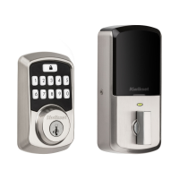
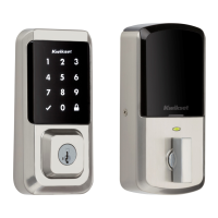
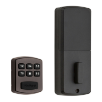
| Type | Deadbolt |
| Keypad | Yes |
| Smart Home Compatibility | No |
| Battery | 4 AA batteries |
| Keyway | KW1 |
| Adjustable Backset | Yes |
| Backset | 2-3/8" or 2-3/4" |
| Door Thickness | 1-3/8" to 1-3/4" |
| Material | Metal |
| Adjustable Latch | Yes |
| Re-keyable | Yes |
| Finish | Satin Nickel |
| Grade | Grade 2 |
| Strike Plate | Reinforced |