EasyManua.ls Logo

Kwikset Smartcode 910 User Manual

Kwikset Smartcode 910
9 pages
To Next Page IconTo Next Page
Page #1 background imageLoading...
Page #1 background image
A
B
W
F
Parts in the box
Latch
“B” is not included. If needed,
please contact Kwikset to order
a drive-in latch for your lock.
Exterior
Assembly
Strike Adapter
ring
C D
E
Keys
Mounting
Plate
SmartKey
Tool
G
H
03809 46780
N
Q
S
P
Fasteners
48654 27526 64109
Interior
Assembly
K L M
T
U V
A
N or P
(2x)
N P
S
Q
A
A
B
B
B
A
B
If drilling a new door, use the supplied template and the complete
door drilling instructions available at www.kwikset.com/doorprep.
Note: Additional door preparation may be
required for doors with 11/2" (38 mm) holes.
Consult the deadbolt drilling instructions at
www.kwikset.com/doorprep.
or
backset
Measure to conirm that the hole in
the door is either 21/8" (54 mm) or
11/2" (38 mm).
Measure to conirm that the backset is
either 23/8" or 23/4" (60 or 70 mm).
23/8" or 23/4"
60 or 70 mm
13/8" – 13/4"*
35 – 44 mm*
Measure to conirm that the hole in
the door edge is 1" (25 mm).
Measure to conirm that the door is
between 13/8" and 13/4"* (35 mm
and 44 mm*) thick.
A
A B
C
D
B C D
Is the door edge chiseled?
Is the D-shaped hole centered in the door hole?
Which latch are you installing?Hold the latch in front of the door hole, with the latch
face lush against the door edge.
21/8"
54 mm
11/2"
38 mm
1"
25 mm
YES
YES
NO
NO
Use latch “A”. If the
latch bolt is not already
extended, extend the
latch bolt as shown.
wood
block
actual
size
Use latch “B” (not
included). If the latch
bolt is not already
extended, extend the
latch bolt as shown.
Latch “A Latch “B”
S (2x)
C
Q (2x)
Longer screws
install closest to
the door jamb.
door frame
E
Install strike on the door frame.
Make sure the hole in the door frame is drilled a
minimum of 1" (25 mm) deep.
or
chiseled
not
chiseled
or
1
Prepare the door and check dimensions
2
Install the latch and strike
*Service kits for 21/4" (57 mm) thick doors
are available through Kwikset.
No adjustment is required.
Proceed to next step.
D-shaped hole D-shaped hole
Rotate latch face as
shown to extend latch.
or
1 / 4
66071001
Rev 01
ZWave® Plus
Installation and User Guide
ENGLISH
Required tools
Ruler4 AA Batteries
Hammer Wood block
Phillips head screwdriver
Additional Tools (depending on application)
Kwikset
Technical Support
1-866-863-6584
www.kwikset.com
Question and Answer IconNeed help?

Do you have a question about the Kwikset Smartcode 910 and is the answer not in the manual?

Kwikset Smartcode 910 Specifications

General IconGeneral
BrandKwikset
ModelSmartcode 910
CategoryLocks
LanguageEnglish

Summary

Prepare the door and check dimensions

Door Hole Diameter Check

Verify the correct diameter for the main door hole.

Backset Measurement

Measure the backset to ensure it fits the latch.

Door Edge Hole Check

Confirm the size of the hole on the door's edge.

Door Thickness Verification

Measure the door's thickness for compatibility.

Install the latch and strike

Latch Installation and Door Edge Condition

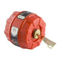
Install the correct latch based on door edge condition.

D-Hole Centering and Latch Selection

Verify D-hole centering and choose the appropriate latch.

Strike Plate Installation

Install the strike plate onto the door frame.

Install the exterior keypad

Cylinder Insertion into Keypad

Insert the cylinder into the exterior keypad assembly.

Exterior Keypad and Mounting Plate Installation

Mount the exterior keypad and its plate to the door.

Install the interior assembly

Prepare Interior Assembly Components

Remove covers, battery, and position turnpiece vertically.

Connect Wiring and Secure Interior Assembly

Connect the cable and attach the interior assembly.

Install batteries and perform door handing

Battery Installation and Handing Initiation

Install batteries and hold lock button to start door handing.

Verify Door Handing Success

Check if the lock successfully completed the door handing process.

Add lock to smart home system

Initiate Smart Home Pairing

Start the pairing process on your smart home controller.

Activate Lock Pairing Mode

Press button 'A' on the lock to enter pairing mode.

Confirm and Finalize Smart Home Pairing

Rename the lock and allow controller to add it.

Add user codes

Initiate User Code Programming

Open door, press Program button for code position.

Enter and Confirm User Code

Input desired user code and press the lock button.

Interpret Programming Feedback

Understand lock's lights/sounds for success or failure.

Test lock operation

Test Locking Functionality

Confirm the lock button functions correctly.

Test Unlocking Functionality

Verify user codes can unlock the door.

Re-key lock and install battery cover

Re-keying the Lock Mechanism

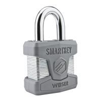
Adjust lock to work with a new key using SmartKey tool.

Install Interior Battery Cover

Secure the interior battery compartment cover.

SmartCode Overview

Exterior and Interior Component Identification

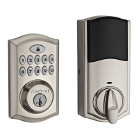
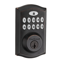
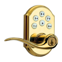
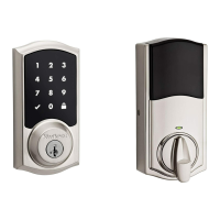
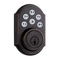
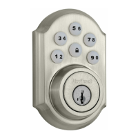
Overview of external and internal parts of the lock.

System Alerts and Troubleshooting Guide

Describes lock alerts, reasons, and solutions.

Switches and Status LED Indicators

Switch Functions and Settings

Explains the purpose of each dipswitch on the lock.

Status LED Color Meanings

Details the meaning of different LED colors and states.

User Code Management

Deleting User Codes

Overwrite existing codes or perform factory reset for deletion.

Factory Reset Procedures

Reset the lock locally or remotely to default settings.

Z-Wave Association Groups

Group 1: Lifeline Association

Explains the Lifeline group and its supported nodes.

Group 2: Doorlock Notify Report

Details the doorlock notification group and capabilities.

Z-Wave Configuration Parameters

User Code Type Configuration (Parameter 1-30)

Sets user type for codes (Owner, Guest, Worker).

User Code Type Details

Valid User Code Types

Lists allowed values for user code types (Owner, Guest, Worker).

User Code Type and Schedule Interaction

Explains how schedules affect user code types and access.

Configuration Parameter 31: Dipswitch Settings

Dipswitch Settings Overview

Controls buzzer and Lock Status LED.

Dipswitch Bit Definitions

Explains meaning of each bit in the dipswitch value.

Configuration Parameters 33 and 34: SKU

SKU Parameter Description

Defines parameters for setting/getting the SKU part number.

Configuration Parameter 40: Factory Reset

Triggering Factory Reset via Parameter 40

Uses parameter 40 to initiate a lock factory reset.

Z-Wave Inclusion Procedures

Adding Lock to Z-Wave Network

Steps to add the lock to a Z-Wave controller.

Z-Wave Exclusion Procedures

Removing Lock from Z-Wave Network

Steps to remove the lock from a Z-Wave controller.

Lock Reset Procedures

Local Factory Reset Method

Detailed steps for performing a local factory reset.

Remote Factory Reset Method

Steps for performing a factory reset via a controller.

Related product manuals