―
11
―
Inthe event of a fault, the Fault loop impedanceshould be lowenough
(andthe Prospective Fault current higher enough) in order to havethe
automaticdisconnectionofsupplybytheinstalledprotectiondevicewithin
prescribedtimeinterval.
Everycircuitmust betested tomake surethat thefault loopimpedance
doesnotexceed thatspecified for theover currentprotectiondevice
concerned.
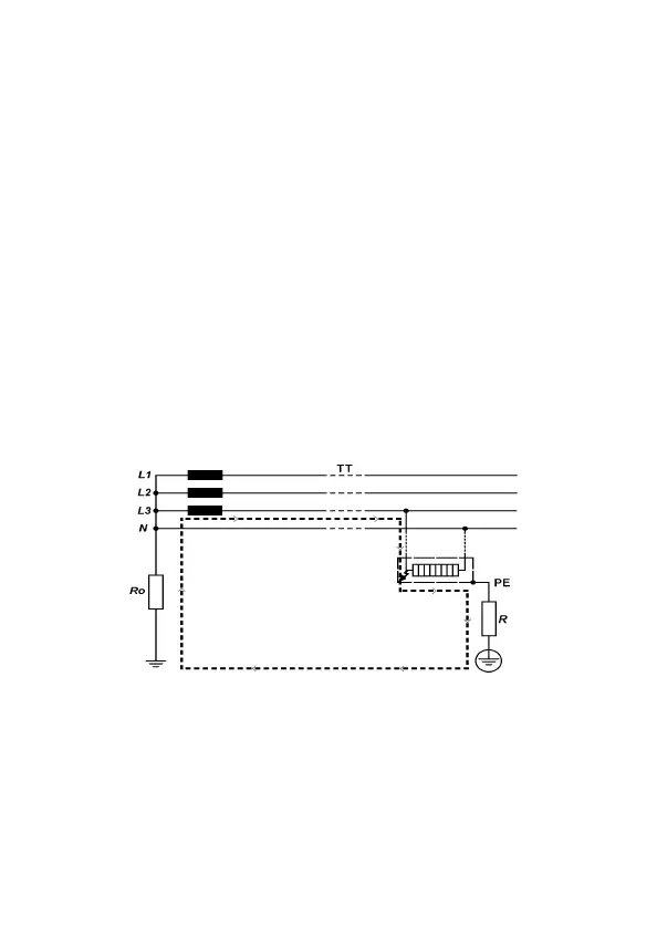
ForTTsystemtheFaultloopimpedanceisthesumofthefollowingpartial
impedances:
¡
Impedanceofpowertransformer'ssecondary.
¡
Phaseconductorresistancefrompowertransformertofaultlocation.
¡
Protectionconductorresistancefromfaultlocationtolocalearth
system.
¡
ResistanceoflocalearthsystemR.
¡
Resistanceofpowertransformer'searthsystemRo.
Thefigure below shows in markedline the Fault loop impedance forTT
system.
Fig.6
ForTNsystemtheFaultloopimpedanceisthesumofthefollowingpartial
impedances:
¡
Impedanceofpowertransformer'ssecondary
¡
Phaseconductorresistancefrompowertransformertofaultlocation
¡
Protectionconductorresistancefromfaultlocationtopowertransformer