―
12
―
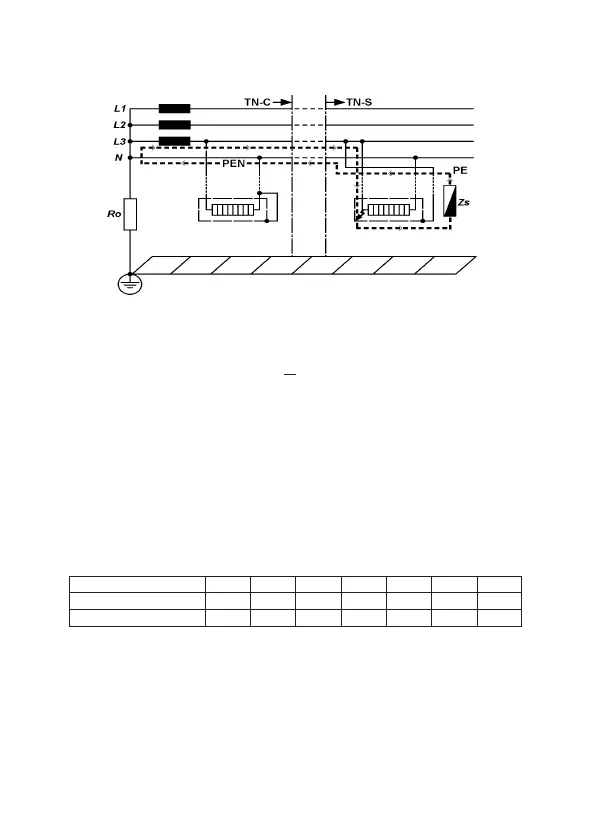
Fig.7
AccordingtotheinternationalStandardIEC60364forTTsystemthe
followingconditionshallbefulfilledforeachcircuit:
RA
<
50/Ia
Where:
¡
RA
isthesum oftheresistances ofthelocal earthsystem Rand
protectionconductorconnectingittotheexposedconductivepart.
¡
50
isthemaxcontactvoltagelimit(itcouldbe25Vinparticularcases)
¡
Ia
isthecurrentcausingtheautomaticdisconnectionoftheprotective
devicewithin5s.
Whentheprotectiondeviceisaresidualcurrentdevice(RCD),
Ia
istherated
residualoperatingcurrentI
⊿
n.
ForinstanceinaTTsystemprotectedbyaRCDthemaxRAvaluesare:
Note:
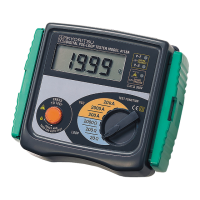
● Theloop tester models 4120A / 4118A / 4116A measure the fault
loopimpedancethatisavaluenormallyalittlebithigherofRA.
But,ifthe electricalinstallation isprotected consideringthe loop
impedancevalue,alsotheRAformulawillbefulfilled.
RatedresidualoperatingcurrentI⊿n.
RA(at50V)
10
5000
2500
30
1667
833
100
500
250
300
167
83
500
100
50
1000
50
25
mA
Ω
Ω
RA(at25V)
Thefigure below shows in marked line the Faultloop impedance for TN
system.