Do you have a question about the KYORITSU KEW 2413F and is the answer not in the manual?
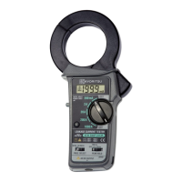
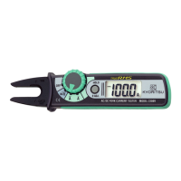
The KEW SNAP Series KEW 2413F is a digital clamp meter designed for both very low and high current measurements. Its shielded transformer jaws minimize the effect of external stray magnetic fields, making it suitable for leakage current measurements.
The KEW 2413F measures AC current from 0.1mA to 1000A. It offers a frequency response higher than 1kHz across all measuring ranges, with approximately 7% accuracy at 20 kHz on the 200mA range.
A key feature is its frequency selector switch, which allows users to choose between "50/60Hz" or "WIDE" settings. The "50/60Hz" position activates an incorporated low-pass filter, enabling current measurement primarily at the mains fundamental frequency. This filters out high-frequency components and harmonics that might be superimposed on the fundamental frequency. The low-pass filter has a cut-off frequency of approximately 100Hz and an attenuation characteristic of approximately -24 dB/octave. The "WIDE" setting (40Hz-over 1kHz) covers a broad frequency band, accommodating measurements from mains supply to high frequencies generated by devices like inverters.
The device also includes a peak-hold facility with selectable response times of 10ms or 100ms. This allows for the capture of peak current values, which are then displayed as 1/√2 of the peak current, providing an RMS reading for sinusoidal waveforms. The peak hold circuit uses an analog design for quick response to input current.
A two-way analog output terminal is provided, offering both AC and DC voltage outputs. The AC voltage output is proportional to the current under test, allowing for waveform monitoring with an oscilloscope or RMS current measurement with a true-RMS-reading instrument. The DC voltage output converts ACA readings, making it suitable for direct connection to devices such as chart recorders. The AC output of the two-way analog output always operates with "WIDE" frequency characteristics, regardless of the frequency selector switch setting. However, the DC output reflects the frequency selector switch setting.
The instrument features a field-effect 3-1/2 digit liquid crystal display with a maximum count of 1999. Function symbols (mA, A) and decimal points appear automatically as the function/range switch is turned. A "B" symbol indicates a low battery warning, and "1" on the highest digit signifies an overrange condition.
Preparation: Before use, the battery status should be checked by setting the function/range switch to any desired position. If the display is clear without the "B" symbol, the battery voltage is sufficient. If the display blanks or shows "B", the battery needs replacement. It's crucial to ensure the data hold button is in the off position (not pressed down) before measurement, as a pressed data hold button will lock the display irrespective of input.
AC Current Measurement: To measure AC current, the function/range switch should be set to the desired position, ensuring the maximum allowable input current for the selected range is not exceeded. The jaw trigger is pressed to open the transformer jaws, which are then clamped onto a single conductor. For accurate readings, it is recommended to place the conductor at the center of the closed transformer jaws. The device can measure earth leakage current or small currents flowing through a grounded wire. For out-of-balance leakage current, all conductors except a grounded wire should be clamped. When measuring large currents, users must observe the specified time limits to prevent transformer jaw overheating and potential instrument damage. The transformer jaws may produce a buzzing sound during large current measurements, which does not affect performance or safety.
Peak Hold Function: To use the peak hold function, the peak hold switch is slid from the OFF position to either the 10ms or 100ms response time position, depending on the application. The 10ms response time is suitable for measuring surge currents when a power supply device is switched on, while the 100ms response time is recommended for starting currents of motors or similar equipment, providing a more stable measurement by not readily responding to surge currents. The displayed reading represents 1/√2 of the peak current. To reset the peak hold, the switch is slid back to the OFF position. If reading the display away from the conductor during peak hold measurement, the data hold switch should be pressed first before removing the instrument from the conductor to avoid higher readings due to electrical noise from jaw opening/closing.
Data Hold Function: The data hold button allows users to freeze the displayed reading. This is particularly useful for taking readings in dimly lit or hard-to-reach locations, as the display can be observed away from the conductor. Pressing the button again releases the reading.
Analog Output: The optional Model 7073 output cord can be inserted into the two-way analog output terminal to obtain AC and DC outputs. The AC output can be connected to a digital multimeter for monitoring or an oscilloscope for waveform observation. For true RMS measurements, a true-RMS-reading digital multimeter should be used. The DC output can be connected to a digital multimeter or a recorder for extended monitoring periods. In peak hold mode, the DC voltage output corresponds to 1/√2 of the peak current value.
Battery Replacement: When the "B" symbol appears on the LCD display, the battery needs to be replaced. First, the function/range switch must be set to the OFF position. Then, the battery compartment cover at the rear of the case is unscrewed and removed. A new 9V battery (type 6F22 or equivalent) is installed, observing correct polarity, and the battery compartment cover is screwed back on. It is critical never to replace the battery during a measurement.
Cleaning: The instrument's body should be cleaned using a damp cloth and detergent. To prevent deforming or discoloring, solutions containing solvents such as paint thinner or benzene must not be used. The instrument is not dust or water-proofed, so it should be kept away from dust and water.
General Care: The transformer jaws, especially their tips, are precisely adjusted for maximum accuracy and should be handled with care to avoid shock, vibration, or excessive force. If a foreign substance prevents the jaws from closing properly, it must be removed carefully without suddenly releasing the jaw trigger or applying external force. The jaws should close by themselves once clear. The maximum conductor size is approximately 68mm in diameter; larger conductors will prevent full jaw closure and lead to inaccurate measurements. The instrument should not be exposed to direct sunlight, extreme temperatures, or dew. After use, the function selector switch should always be set to the "OFF" position. For long-term storage, the battery should be removed to prevent damage from leakage. The instrument should only be used in its intended applications and conditions; otherwise, safety functions may not work, potentially causing injury or damage. Never apply voltage to the OUTPUT terminal, as it is not electrically isolated from the internal circuits.
| Category | Measuring Instruments |
|---|---|
| Model | KEW 2413F |
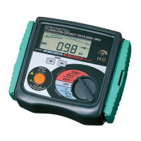
| Type | Digital Insulation Tester |
| Weight | 1.5 kg |
| Dimensions | 250 x 130 x 80 mm |
| Display | LCD |
| Safety Standards | IEC 61010-1 CAT III 600V |
| Frequency Response | 40Hz |
| Voltage Range/Test Voltage | 50V, 100V, 250V, 500V, 1000V |
| Battery Type | AA alkaline batteries (1.5V) × 8 |
| AC Current | Not Applicable |
| AC Current Accuracy | Not Applicable |
| Withstand Voltage | Not Applicable |
| Power Source | AA alkaline batteries (1.5V) × 8 |