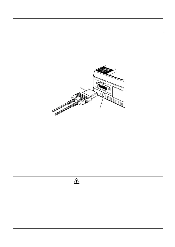
5-1Testleadconnection
Insert theProbeconnector into the Probe socket on the instrument
correctlyasshownbelow.
5-2 ChecksonTestleadandFuse
(1)SettheRangeselectorswitchontheinstrumenttotheΩ
(CONTINUITY)position.
(2)Breakintestleadorfuseissuspectedif"OL"isdisplayedonthe
LCDwhenshortingtheLINE(red)andEARTH(black).
(3)Testleador instrumentitselfmayhavetroubles when"OL" is
displayedontheLCDafterreplacingthefuse.Inthiscase,send
theinstrumenttoyourlocalKYORITSUdistributorforrepair.
DANGER
¡
WhentheTest buttonor theRemotecontrol switchispressed
whiletheRangeselectorswitch settoaninsulationresistance
range,takecarenottotouchthetipoftheTestprobewhereahigh
voltageispresentinordertoavoidpossibleshockhazard.
¡
Testleadandfusemustbeinspectedpriortomeasurement
accordingtoClause5-2indicatedinthismanualinordertoavoid
possibleelectricalshockhazard.Voltagecannotbemeasuredifa
breakispresentonthefuse.
―9―
 Loading...