ESI-500
Pilot’s Guide3-2
Display Features
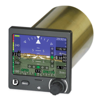
Pitch Ladder
The pitch ladder scale is located in the center of the display with short
horizontal lines positioned at +/- 2.5° and +/-7.5°, medium horizontal
lines positioned every +/-5°, and long horizontal lines positioned every
+/- 10°. The pitch ladder rotates around the aircraft reference symbol
in relation to aircraft’s roll and scrolls up and down in response to the
aircraft’s pitch. The scale has a maximum pitch of +/- 90°.
Pitch tape chevrons are displayed such that at least one pitch tape
chevron, pointing towards the zero pitch line, is visible when the pitch
tape contains pitch values (less than or equal to -25°) or (greater than
or equal to 35°).
Roll Indicator
The roll indicator con
sists of a roll scale and a roll pointer. White scale
lines are set at +/- 10°, 20°, and 30°. Hollow triangles are set at 45°
and a solid downward white triangle representing the 0° mark. The roll
pointer is an upward pointing triangle located on the inner arc radius of
the roll scale. Release 1.3 and greater has white scale lines at +/- 60°
that come into view when the aircraft is in a roll.
The roll pointer can be congured to be xed (scale moves) or
moveable (pointer moves). The roll pointer or roll scale rotate +/- 180°
around the aircraft reference symbol boresight.
Aircraft Reference Symbol
The aircraft reference symbol is xed in the center of the display and
provides a reference to determine the aircraft’s pitch and roll. The
aircraft is at a zero degree pitch when the horizon line intersects the
aircraft reference symbol’s boresight.
Slip/Skid Indicator
The slip/skid indicator is l
ocated at the base of the roll pointer and
moves laterally with respect to the roll pointer proportionally to
lateral acceleration. The slip indicator is depicted as a trapezoid. A
displacement the width of the trapezoid (from the midpoint of the left
side to the midpoint of the right side) is approximately equivalent to
one ball displacement of a conventional inclinometer. For Release 1.1
the slip/skid indicator has a range of ±12°. For Release 1.2 the range is
congurable at installation for ±12° or ±7°
Attitude Invalidity
The pitch tape, roll scale, roll pointer, and slip/skid indicator are
removed from the display and replaced with an attitude failure message
“ATT FAIL” when invalid attitude data is detected. See Chapter 4 for
details.