Pilot’s Guide v
List of Illustrations
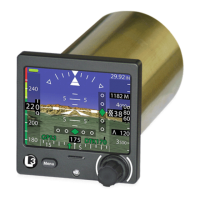
Figure 1-1: ESI-500 ....................................................................... 1-1
Figure 2-1: Example of Attitude Aligning........................................ 2-2
Figure 2-2: Example of Normal Display and
Synthetic Vision Display ............................................. 2-3
Figure 3-1: Attitude Display Features ............................................ 3-1
Figure 3-2: Airspeed Display Features .......................................... 3-3
Figure 3-3:
V
NE
Awareness Color Bar Cues ................................... 3-5
Figure 3-4:
V
NE
Power On
Awareness Color Bar Cues .................... 3-5
Figure 3-5:
V
MO
Awareness Color Bar Cues ................................... 3-6
Figure 3-6: Altitude, Baro, and Vertical Speed Display Features... 3-7
Figure 3-7: Direction Display Features .......................................... 3-9
Figure 3-8: Air Temperature Display ..............................................3-11
Figure 3-9: True Airspeed Display .................................................3-11
Figure 3-10: VOR Display Features ............................................ 3-13
Figure 3-11: ILS/LOC Display Features ....................................... 3-13
Figure 3-12: GPS Display Features............................................. 3-14
Figure 3-13: Examples of VOR TO/FROM Transition .................. 3-17
Figure 3-13: Example of Marker Beacon ..................................... 3-17
Figure 3-15: Synthetic Vision Display Features ........................... 3-20
Figure 3-16: SVS % ...................................................................... 3-21
Figure 3-17: Example of Grid Line Overlay ................................ 3-21
Figure 3-18: Terrain Caution Alert ................................................. 3-22
Figure 3-19: Terrain Warning Alert ................................................ 3-22
Figure 3-20: Obstacle Alerts ......................................................... 3-23
Figure 3-21: Phase of Flight Denitions ....................................... 3-24
Figure 3-22: Reduced RTC Alert Condition .................................. 3-25
Figure 3-23: ITI Alert Condition..................................................... 3-26
Figure 3-24: SVS Invalidity ........................................................... 3-27
Figure 4-1: Display Invalidities ...................................................... 4-1
List of Tables
Table 1-1: ESI-500 .......................................................................... 1-1
Table 2-1: Pilot Menu List ............................................................... 2-5
Table 3-1: Required Terrain Clearances for the
Reduced RTC Alert Condition ..................................... 3-25
Table 3-2: Required Terrain Clearances for the
ITI Alert Condition ........................................................ 3-26
Table 4-1: Indications and Display Conditions ................................ 4-2
Table 4-2: Battery Indications ......................................................... 4-8