L-ACOUSTICS MTD Manual V1.2 11/30/2004 4
6. INSTALLATION PROCEDURES .......................................................................................................51
6.1 ETR8 U-BRACKET ATTACHMENT(MTD108a) ........................................................................................... 51
6.2 ETR1, ETR2 U-BRACKET ATTACHMENT (MTD112b, MTD115b) ...............................................................52
6.3 OMNIMOUNT BRACKET ATTACHMENT (MTD112b, MTD115b) ..............................................................53
6.4 SAFETY RULES ........................................................................................................................................... 53
7. MTD SYSTEM OPERATION..............................................................................................................54
7.1 RECOMMENDED MAINTENANCE PROCEDURES ..................................................................................... 54
7.2 SPARE PARTS.............................................................................................................................................. 55
8. SPECIFICATIONS ..............................................................................................................................56
8.1 MTD108a SPECIFICATIONS....................................................................................................................... 56
8.2 MTD108LLCa SPECIFICATIONS ................................................................................................................. 59
8.3 MTD112b SPECIFICATIONS....................................................................................................................... 60
8.4 LLC112b-st SPECIFICATIONS ..................................................................................................................... 63
8.5 MTD115b SPECIFICATIONS....................................................................................................................... 64
8.6 LLC115b-st, LLC115b-2w SPECIFICATIONS................................................................................................ 67
LIST OF FIGURES
Figure 1: MTD System Components........................................................................................................9
Figure 2: MTD LLC Controllers .............................................................................................................11
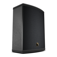
Figure 3: MTD108a passive 2-way (8” LF + 1” HF) coaxial loudspeaker..............................................13
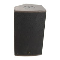
Figure 4: MTD112b passive 2-way (12” LF + 1.4” HF) coaxial loudspeaker ........................................14
Figure 5: MTD115b active/passive 2-way (15” LF + 1.4” HF) coaxial loudspeaker..............................15
Figure 6: MLS switches on the rear panel of L-ACOUSTICS LA24a, LA48a amplifiers.........................16
Figure 7a: MTD108a Floor Monitor System Block Diagram ..................................................................27
Figure 7b: MTD108a Floor Monitor System Cabling Detail...................................................................27
Figure 8a: MTD108a FOH System Block Diagram (mono subwoofers)................................................28
Figure 8b: MTD108a FOH System Cabling Detail (mono subwoofers).................................................28
Figure 9a: MTD108a FOH System Block Diagram (stereo subwoofers) ...............................................29
Figure 9b: MTD108a FOH System Cabling Detail (stereo subwoofers)................................................29
Figure 10a: MTD112b Floor Monitor System Block Diagram................................................................30
Figure 10b: MTD112b Floor Monitor System Cabling Detail ................................................................30
Figure 11a: MTD112b FOH System Block Diagram (mono subwoofers)..............................................31
Figure 11b: MTD112b FOH System Cabling Detail (mono subwoofers) ..............................................31
Figure 12a: MTD112b FOH System Block Diagram (stereo subwoofers).............................................32
Figure 12b: MTD112b FOH System Cabling Detail (stereo subwoofers) ............................................32
Figure 13a: MTD115b (passive) Floor Monitor System Block Diagram.................................................33
Figure 13b: MTD115b (passive) Floor Monitor System Cabling Detail .................................................33
Figure 14a: MTD115b (passive) FOH System Block Diagram (mono subwoofers) ..............................34
Figure 14b: MTD115b (passive) FOH System Cabling Detail (mono subwoofers) ...............................34
Figure 15a: MTD115b (passive) FOH System Block Diagram (stereo subwoofers)..............................35
Figure 15b: MTD112b (passive) FOH System Cabling Detail (stereo subwoofers) ..............................35
Figure 16a: MTD115b (active) Floor Monitor System Block Diagram...................................................36
Figure 16b: MTD115b (active) Floor Monitor System Cabling Detail ...................................................36
Figure 17a: MTD115b (active) FOH System Block Diagram (mono subwoofers).................................37
Figure 17b: MTD115b (active) FOH System Cabling Detail (mono subwoofers) ................................37
Figure 18a: MTD115b (active) FOH System Block Diagram (stereo subwoofers)................................38
Figure 18b: MTD112b (active) FOH System Cabling Detail (stereo subwoofers)................................38
Figure 19: General guidelines for aiming MTD enclosures.....................................................................40
Figure 20: SPL mappings at octave band frequencies for a single MTD enclosure ................................40
Figure 21: SPL mappings for two MTD enclosures with 0.5 metre spacing ..........................................41
Figure 22: SPL mappings for two MTD enclosures with 3 metre spacing .............................................41
Figure 23: General guidelines for arraying MTD enclosures. .................................................................42
 Loading...