L-ACOUSTICS MTD Manual V1.2 11/30/2004 50
5.8.3 Separate Flown MTD with Ground Stacked Subwoofers
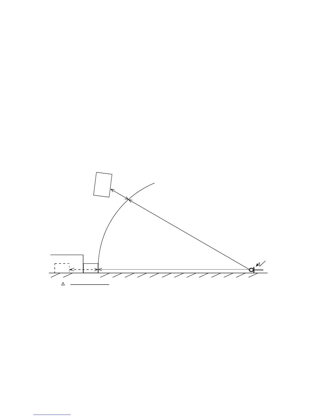
For a separate flown MTD system with ground stacked subwoofers, time alignment of subwoofers is
required due to the geometric path difference between the two systems. This is illustrated in Figure
26, where the distance from the measurement microphone position to the subwoofers is d
SUB
while
the distance to the flown MTD system: d
FLOWN
= d
SUB
+ PATH DIFFERENCE. Delaying the
subwoofers by the geometric path difference will time align the subwoofers at the reference position.
Note: Selection of the reference position for time alignment is always a compromise since the geometric
path difference will vary with position.
Note: A separate digital delay unit will be required for subwoofer time alignment.
In most cases, LLC controllers should be used in X-OVER mode for flown MTD and ground stacked
subwoofer configurations in (3-way mode or with separate AUX drive for the subwoofers) since the
subwoofers can be used with positive polarity and this helps to simplify installation and system tuning.
However, if more low frequency energy is desired from the flown MTD system, FRONT or
MONITOR settings can be used and subwoofer polarity will depend on how subwoofers are
processed, i.e., whether they are driven with the same signal as the MTD enclosure or driven via
discrete AUX send. Following time alignment, subwoofer polarity is a parameter to experiment with
in order to obtain the best results.
STAGE
PATH
DIFFERENCE
MEASUREMENT
MICROPHONE
FLOOR
TIME DELAY
(SB218)
(FLOWN
SYSTEM)
d
sub (m)
d
FLOWN=
d+
SUB
PATH DIFFERENCE
d
su
b
(m
)
(SB218)
PATH DIFFRENCE (meters)
343
 Loading...