COMPONENT MAINTENANCE MANUAL
AVIATION PRODUCTS
Model FA5000
Assembly
23–70–30
Use or disclosure of information on this sheet is subject to
the restrictions on the cover page of this document.
Rev. 02 Page 704
July 21/17
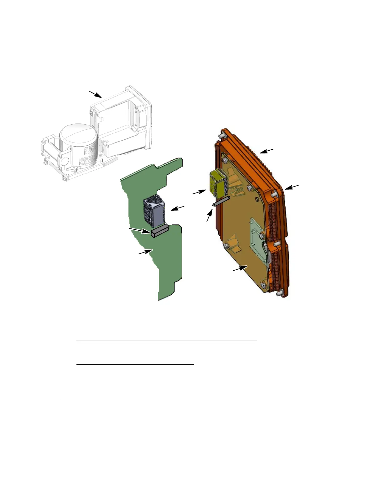
rear cover (1−10) to the rear part of the Shielded Housing (1−5). Tighten
screws to a torque value of 9−10 in./lbs.
(Qty. 6)
(1−10)
(1−25)
Some parts are removed
for clarity purposes
NOTE:
Connector
(1−45)
(1−5)
(REF,)
Guide Pin
Receptacle
(1−15)
Torque
(9−10in/lbs)
Figure 702.
Rear Cover Installation Diagram
D. Crash Survivable Memory Unit (CSMU) Installation
(See Figure 703 or IPL Figure 1, Item 185)
CSMU INSTALLATION PROCEDURE
(1) Carefully guide the CSMU (1−120) cable thru the slot in the front chassis
(1−95).
NOTE
: Apply Loctite to all screw installations for the following proced-
ures:
(2) Install the four screws (1−125) used to secure the CSMU (1−120) to the front
chassis (1−95). Torque mounting bolts (1-125) in a cross−pattern as shown in
Figure 704 to 75 in/lbs.
The document reference is online, please check the correspondence between the online documentation and the printed version.