Do you have a question about the L3 FA5000 and is the answer not in the manual?
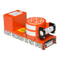
Provides an overview of the FA5000 CVR and its features.
Explains the "ON CONDITION LRU" design and field repairability.
Details the organization and content of the CMM.
Describes the FA5000 CVR, its features, and general capabilities.
Explains the system's inputs, outputs, and overall architecture.
Describes each software task comprising the FA5000 CVR.
Lists system specifications and relevant technical standards.
Explains the system architecture, subassemblies, and interfaces.
Provides operational testing procedures using CATS software and ROC/7.
Describes the pre-flight functional checkout using front panel controls.
Provides instructions for connecting the RIU to ROC/7 and FA5000 CVR.
Provides step-by-step instructions for performing the CATS Autotest.
Details troubleshooting steps for the main processor and associated components.
Provides troubleshooting guidance for the CSMU and its memory components.
Provides information required to disassemble FA5000 recorders and general precautions.
Details procedures for removing the RIPS module, including its battery.
Provides specific instructions for disassembling the FA5000.
Procedure for removing the CSMU, referencing figures and IPL.
Step-by-step procedure for removing the rear cover.
Provides warnings and cautions for cleaning operations.
Details cleaning the ULB water switch and case without disassembly.
Lists checks for the main recorder assembly and mechanical inspection.
Inspects parts for cracks, wear, finish, and solder joints.
Recommends testing the ULB every 24 months as per specific manuals.
Provides general assembly instructions and ESD precautions.
Details the procedure for installing the AI PWA onto the rear cover.
Details the RIPS module's function, shelf life, and connector covers.
Steps for installing the RIPS module into the CVDR.
Guidelines for storing the equipment, both in original and alternative containers.
Details the physical dimensions, weight, and markings of the FA5000.
Specifies electrical characteristics including power, input/output, and signal formats.
Details environmental specifications for CSMU assembly survival under crash/fire conditions.
Lists required tools, fixtures, and equipment for FA5000CVR testing.
Describes the ROC/7 test setup and its components for FA5000CVR testing.
Describes the ADLP software for audio/datalink retrieval and playback.
Explains the structure of the IPL: intro, designator list, numerical index.
Contains illustrations and breakdown of component parts, assemblies, and subassemblies.
Lists current configurations for FA5000 CVR and FDR models.
| Brand | L3 |
|---|---|
| Model | FA5000 |
| Category | Voice Recorder |
| Language | English |