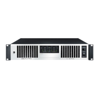
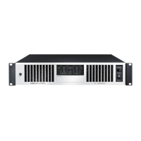
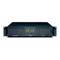
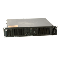
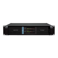
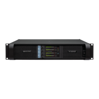
12 CA SERIES Quick Start Guide 13
CA Series Getting started
Welcome to the CA series Quick Start Guide and thank you for purchasing one of
these ampliers. The following accessories should be included with your product:
• Euroblock input connector(s)
• Euroblock output connector
• Coupling plate (x2) with necessary screws
• Long angle bracket
• Front angle bracket (x2)
• Rear at bracket
• Rear angle bracket with shoulder screw
• Power cable with mains plug corresponding to the specied country version
• Quick Start Guide (this document)
Rack Mounting
The CA series ampliers come with rubber feet that enable the amps to be
placed on a clear surface without an additional installation. However, optional
rack mounting hardware is also supplied, allowing several models to be housed
and protected inside an enclosure. Follow these steps to attach the mounting
hardware.
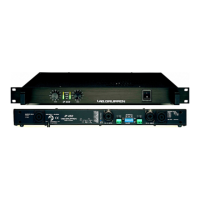
A pair of CA units can be mounted side-by-side to occupy a single rack space.
Attach the coupling plate to the underside of 2 CA units using the included
screws.
Attach the front angle brackets to either side of a pair of CA units that have been
coupled. Alternatively, a single CA unit can be installed in a 19" rack using the
long angle bracket, or in a half
19" rack using the short angled brackets.
Attach the angled brackets, by unscrewing the chassis side front screws and
attach again together with the brackets.
If your rack has rear rails, attach the rear at brackets by reusing the screws from
the chassis.
Mount the CA units into the rack by attaching 4 rack screws through the front
angle brackets and rack rails.
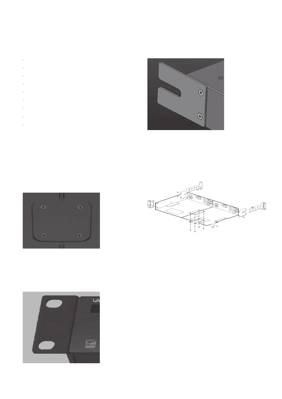
Hold one of the rear angle brackets up to the rear rack rails so that it lines up next
to the rear at bracket. Do not attach it to the rear rails yet.
Insert the included shoulder screw through the slot in the rear at bracket and
into one of the threaded holes in the rear angle bracket. The screw should allow
the rear angle bracket to slide forward and back within the at bracket’s slot.
Repeat the process for the other rear angle bracket.
Mount the rear angle brackets to the rear rack rails using 4 standard rack screws.
Tighten the shoulder screw if necessary.
The standard rack screw is M4 x 8mm.
The CA series ampliers are convection cooled and primarily use the top surface
to dissipate heat. For demanding applications, it is recommended to have
sucient space (1 RU) above the amplier to reduce the risk of limiting due to
overheating.
Table/Wall Mounting
Connect a pair of coupling plates to either side of a CA series amplier, then
mount screws through the remaining holes in the plates to secure the unit to a
wall or table.
Connections
For balanced input connections, use a 3-pole cable (hot, cold, ground) wired to a
Euroblock connector. Alternatively, RCA cables can be connected for unbalanced
stereo sources, but the RCA and Euroblock inputs should not be used together on
the same input. Note that stereo RCA signals will be summed to mono.
For output signals, connect a 4-pole (2-pole for CA601/1201/2401) Euroblock
connector to the main output connector. Do NOT connect any terminal to ground.
Do NOT connect the cold (-) terminals together for common returns. Make sure to
set the Cong switches in the correct position to match your intended use.
Speaker wire of 14-18 AWG (0.8 to 2.5 mm) is recommended for connections up
to 50 feet.
Cong
The rst 2 Cong dipswitches allow the output to be congured for 100 V, 70 V, 8
Ω, or 4 Ω operation. Always use the correct conguration for the speakers being
driven! The mode of operation congures both the maximum voltage of the
output and the gain through the device.
The 8 Ω setting should be used for a pair of 16 Ω speakers or a single 8 Ω speaker.
The 4 Ω setting should be used for 4 x 16 Ω, 2 x 8 Ω, or a single 4 Ω speaker. Use 70
or 100V setting for Constant Voltage high impedance speaker systems. Make sure
the sum of the power tapping on the speakers plus margin does not exceed the
amplier's maximum power rating.
The 3rd dipswitch engages a high-pass lter at 80 Hz, which should be used on
all Constant Voltage systems to avoid saturation on the transformer-enabled
speakers, but can also be used to help maintain clear sound from small speakers
or bass-heavy audio.
Remote
RJ45 receptacle to connect an optional remote volume control per channel.
Use a standard cable to connect the CRC-V accessory. Or connect a custom
potentiometer with the pinout information. Cable length above 305m (1000ft) is
not recommended.
Signal Wake-up
If the amps are powered on, but do not receive any input signal (below signal
present level) for 20 minutes, the system will enter standby mode to save power
consumption. As soon as a signal is detected at any input, the unit will exit
standby mode and resume normal function.
 Loading...