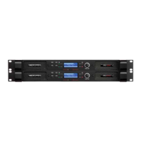
Figure 5. Rear panel connectors
Do not use XLR and TRS jacks on the same
channel simultaneously for mixing or other
purposes.
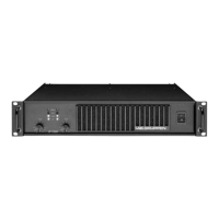
Figure 6. Balanced line
To connect an unbalanced source, tie pin 3 (ring on
TRS jack) down to the shield of the connector. If you
leave one pin disconnected, you will lose 6 dB in
gain.
Figure 7. Unbalanced line connection
A more optimal method for handling unbalanced
sources is shown in Figure 8. This is similar to the
connection for balanced lines, but pin 3 is tied down
to shield, at the source side instead. The hum and
noise rejection for the cable is equivalent to that for a
balanced line. To minimize hum in the audio, use
balanced inputs whenever possible.
Fi
gure 8. Balanced line with unbalanced equipment
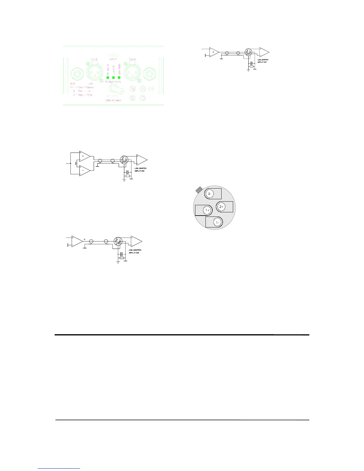
7. Connecting speakers
Speaker connections are made via the two Neutrik
NL4FC Speakon connectors (1).
They are the only connectors currently available to
meet the EC safety requirements. They are wired in
the following manner:
Pin -1 Speaker ground.
Pin +1 Speaker positive.
Pin -2 No connection.
Pin +2 No connection.
Figure 9. Speakon connector
Please note that this is the standard wiring
convention for Speakon connectors adopted world-
wide.
Never connect either output terminal to ground
or to some other output or input terminal (see
warning on page 2).
For normal two-channel operation, connect each
speaker load across the outputs positive and ground
terminals. Pay attention to speaker polarity;
loudspeakers connected out of polarity degrade
sound quality and may be damaged as a
consequence.
Keep the speaker cable wires as short as possible,
and use a good quality stranded speaker cable. Do
not use shielded wire, such as microphone or guitar
cable. Remember that the speaker cable robs the
power of the amplifiers in two ways:
Increases the load impedance and introduces
resistive power losses, so called I
2
R losses.
Operation modes
1. Stereo operation
For stereo (dual channel ) operation, leave the Link
and Phase reverse switches in the undepressed
position. In this mode, both channels operate
independently of each other, with their level
attenuators controlling their respective levels.
Never connect either output terminal to ground
or in parallel. The recommended minimum
nominal impedance, for stereo or tandem operation,
is 2 ohms per channel.
2. Tandem mono
For tandem ( dual channel-single input) operation ,
depress the Link switch. Both channels can now be
driven by a signal, at either input connector. The
output connection is the same as in stereo mode.
You can use either TRS connectors for linking out
etc. Do not use the remaining XLR and TRS
connectors for mixing or other purposes. Both
6

 Loading...