level attenuators are active, allowing you to set
different levels for each channel.
Never connect either output terminal to ground
or in parallel.
3. Bridged mono
To bridge the amplifier, depress the Link switch (6)
and Phase reverse switch (5). Both channels are then
driven by a single signal at either input. You can
use any remaining input connectors for linking etc.
Do not use the remaining XLR and TRS as input
jacks simultaneously for mixing or other purposes.
To obtain an output, connect the speaker leads to pin
+1 on channel A Speakon to speaker positive
terminal and pin +1 on channel B Speakon to
speaker negative terminal . Do not connect either
of the -1 (negative) pins of the Speakons. Do not
connect speakers to channel A or B in the normal
manner in bridge mode, as this can cause serious
damage.
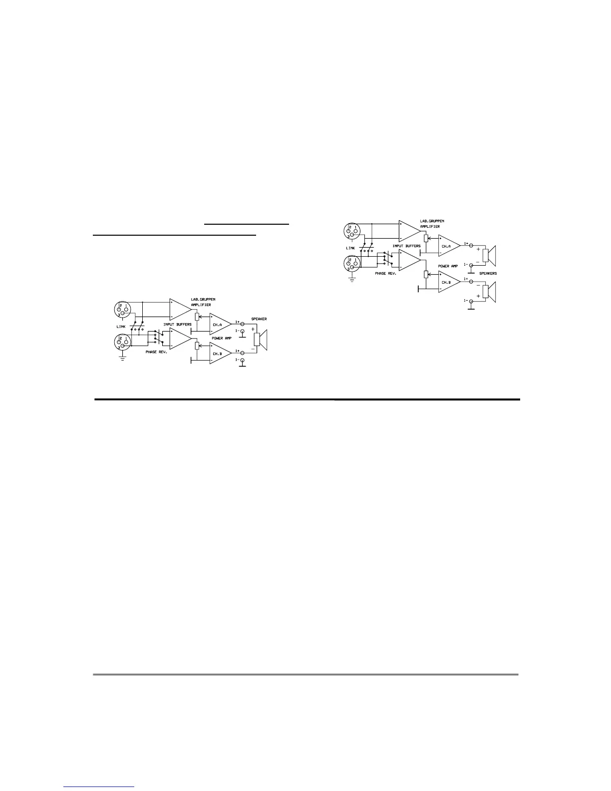
Figure 10. Bridge mono connection
The recommended minimum nominal impedance
for bridged mono is 4 ohms (equivalent to driving
both channels at 2 ohms).
Driving bridged loads of less than 4 ohms may cause
a thermal overload.
Both level attenuators must be at the same position.
We recommend you to put them in the 0 dB (full)
position.
4. Stereo reverse
This mode is similar to the Tandem mono mode.
Apart from depressing the Link switch , you also
depress the Phase reverse switch, like in the Bridge
mono. Channel B is now phase reversed. To
compensate for that, connect pin +1 on channel B
Speakon to speaker negative terminal and pin -1
on channel B to speaker positive terminal.
Figure 11. Stereo reverse mode
Channel A output is connected as in the normal
stereo mode. By having channel A and B operating
in opposite polarity, the energy storage in the
power supply is more efficient. This means that the
amplifier can deliver up to 10% more power than in
tandem mono mode. This is significant for signals
below 100 Hz (sub bass etc.).
Operation
1. Operation precautions
• Make sure that the power switch is off before
making any input or output connections or
operating the switches on rear panel. See pages
4-5 about installation.
• Make sure that the AC mains is correct and the
same as that is printed on the rear panel of the
amplifier. See pages 4-5 , about operating
voltage and power consumption.
• Make sure that the switches on the rear panel
for operation modes ,clip limiters, etc. are in
the correct position. See pages 6-7, about
operation modes and page 8 about clip limiters.
• It is always a good idea to turn down the gain
controls during power up, to prevent speaker
damage, if there is a high signal level at the
input.
2. Input attenuators
The two input level attenuators on the front
panel, alter the signal level for their respective
amplifier channel in all modes. They are calibrated in
dB to help setting up active loudspeaker systems or
cutting down unwanted noise from the input signal.
In bridged mode, both controls must be in the same
position, so that the speaker load will be shared
equally between the channels.
3. Gain switch
The gain switch located on rear panel is for
changing the input sensitivity of the amplifier. This
can be handy when using low or high nominal input
signals e.g. most professional mixing consoles
operate at a nominal level of +4dBu therefore use the
29dB position (depressed switch), to give you plenty
of fader movement. On the other hand, for a disco
mixer that operates at a nominal level of 0dBu, use
the upper position setting, which has a sensitivity of
0 dB for full power in 4 ohms.
7

 Loading...