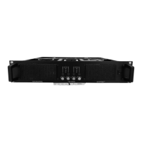
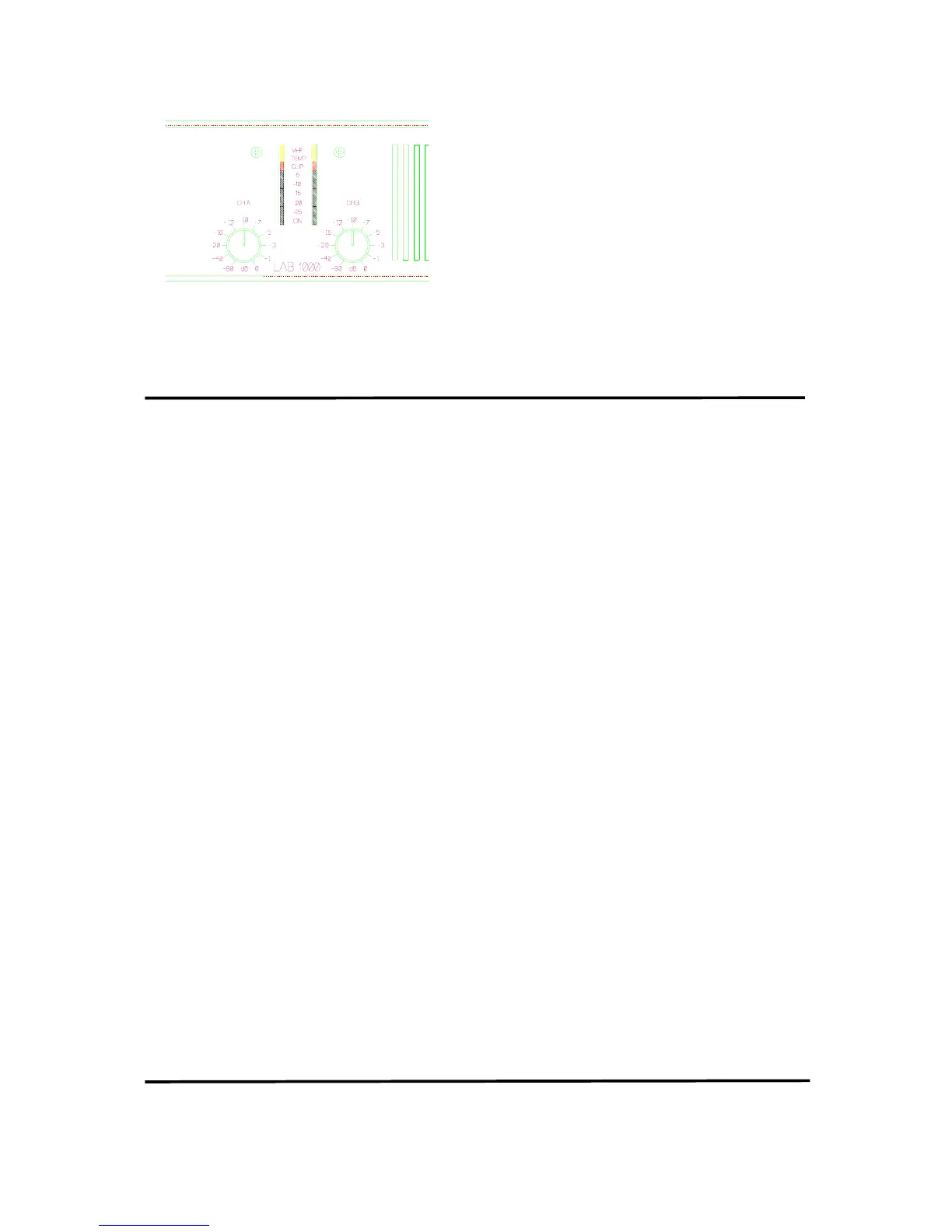
Figure 12. Front indicators
4. Indicators
The two bottom green ”ON” LEDs indicate that the
output circuits are receiving the correct rail voltage.
The ”-25 dB” LEDs glow when the output signal is
greater than -25dB, 0dB is referenced to full output
power. These LEDs also act as signal present
indicators. The rest of the green LEDs forms a bar
for output levels from -20dB to -5dB.
The Clip/limit indicator tells when the amplifier
output is clipping or limiting. The two different states
can be told apart:
• When the clip limiter is engaged it flickers
briefly.
• When the clip limiter is not engaged it lights for
a longer period.
The remaining yellow LEDs indicate if any
protection circuits are activated. These are described
below.
Protection features
Each LAB.GRUPPEN amplifier has many advanced
protection features, that will protect both the
amplifier and the speakers connected to it, should a
fault condition arise. Under normal use these features
are inaudible. All protection circuits are independent.
Clip limiter
The clip limiter is included to prevent dangerous clip
signals reaching the speaker and damaging it. It
works by monitoring the output and comparing the
distortion produced between the input and output of
the amplifier. If the distortion exceeds 1%THD for
any reason ( voltage or current clipping), the limiter
reduces the input signal proportionally. Note that, if
the signal is distorted or clipped before it reaches the
amplifier, the clip limiter will not be activated. Under
normal operation the clip limiting is inaudible. The
limiter can be turned On or Off by depressing the
relevant clip limit switch (2). Some manufacturers of
Loudspeaker processors do not recommend the use
of clip limiters in amplifiers, as they tend to upset the
tracking of the processor’s limiters. Apart from this
one exception, LAB.GRUPPEN recommend
leaving the clip limiters switched "on" (button
depressed).
As a by-product, when the amplifier comes out of a
protect condition, the output level has a slow rise
time -the effect is like turning the gain up slowly.
Thermal protection
When the amplifier is driven very hard into low
impedance, the cooling fans go into high speed. If the
conditions that cause this continue, the temperature
indicator(s) will light as an indication that the
amplifier will soon thermal out.
After five seconds the amplifier will go into thermal
protect, by muting the input signal. After 15-20
seconds the amplifier will cool down the
Intercooler
®
and the cycle will begin again.
Thermal protection starts when the Intercooler
®
reaches a temperature above 90
0
C
VHF protection
When a signal of more than 20khz, at full output
power, is present at the output connectors for more
than five seconds, the VHF protection mutes the
input signal (this is indicated on the front panel (4)
labeled VHF). After five seconds the cycle starts
again.
If the VHF protection is required to be turned off i.e.
for studio monitors, please consult your supplier, as
this is a non-user adjustment.
Short circuit protection
All LAB.GRUPPEN amplifiers are completely
short circuit protected. The protection circuit
permits very high peak currents, but still holds the
output devices within the safe operation area. If a
short circuit is maintained, the channel affected will
eventually go into thermal protection and the cycle
will start again.
D.C. protection
There are two types of DC protection:
Fuses on the supply branches of each channel (this is
an IEC 65 requirement).
A Crowbar bar protection that shorts the output. Both
these circuits come into effect once a DC level of 10
volts or more is detected on either channel.
Design features
Cooling
8
The LAB.GRUPPEN amplifier runs very cool due
to a patented heat sink called Intercooler
TM
. The
output devices (bi-polar) are mounted directly on a
copper heat sink thereby avoiding thermal losses
normally found when using mica washers (the heat
sink is mounted horizontally in front of a pressure
chamber) The air flow is constant along the whole
heat sink,

 Loading...