PAGE 13
METER PLUG
Item No. Quantity Part No. Description
1 1 V3151 Nut 1” QC
2 1 V3105 O-Ring 215
3 1 V3003 Meter Plug Assembly
BRINE REFILL
Item No. Quantity Part No. Description
1 1 H4615 Elbow Locking Clip
2 1 H4614 Polytube Insert 3/8”
WS1 & WS1.25 Drawings & Service Manual Page 15
Drain Line – 3/4”
Water
Flow
Proper DLFC orientation
directs water ow towards
the washer face with
rounded edge.
Drawing No. Order No. Description Quantity
1 H4615 Elbow Locking Clip 1
2 PKP10TS8-BULK Polytube insert 5/8 Option
3 V3192 WS1 Nut ¾ Drain Elbow Option
4* V3158-01 WS1 Drain Elbow ¾ Male 1
5 V3163 O-ring 019 1
6* V3159-01 WS1 DLFC Retainer ASY 1
7
V3162-007 WS1 DLFC 0.7 gpm for ¾
One DLFC
must be
used if ¾
tting is
used
V3162-010 WS1 DLFC 1.0 gpm for ¾
V3162-013 WS1 DLFC 1.3 gpm for ¾
V3162-017 WS1 DLFC 1.7 gpm for ¾
V3162-022 WS1 DLFC 2.2 gpm for ¾
V3162-027 WS1 DLFC 2.7 gpm for ¾
V3162-032 WS1 DLFC 3.2 gpm for ¾
V3162-042 WS1 DLFC 4.2 gpm for ¾
V3162-053 WS1 DLFC 5.3 gpm for ¾
V3162-065 WS1 DLFC 6.5 gpm for ¾
V3162-075 WS1 DLFC 7.5 gpm for ¾
V3162-090 WS1 DLFC 9.0 gpm for ¾
V3162-100 WS1 DLFC 10.0 gpm for ¾
Valves are shipped without drain line ow control (DLFC) - install DLFC before using. Valves
are shipped without ¾ nut for drain elbow (polytube installation only) and 5/8" polytube insert
(polytube installation only).
4
*4 and 6 can be ordered as a complete assembly - V3331 WS1 Drain Elbow and Retainer Asy
DRAIN LINE - 3/4”
Item no. Quantity Part No. Description
1 1 H4615 Elbow Locking Clip
2 1 V3194 Polytube Insert 5/8
3 1 V3192 Nut for 3/4 Drain Elbow
4 1 V3158 3/4 Drain Elbow
5 1 V3163 O-Ring 019
6 1 V3159 DLFC Retainer
7 1 V3162-056 DLFC 5.3
7 1 V3162-065 DLFC 6.5
7 1 V3162-090 DLFC 9.0
7 1 V3162-100 DLFC 10.0
WS1 & WS1.25 Drawings & Service Manual Page 17
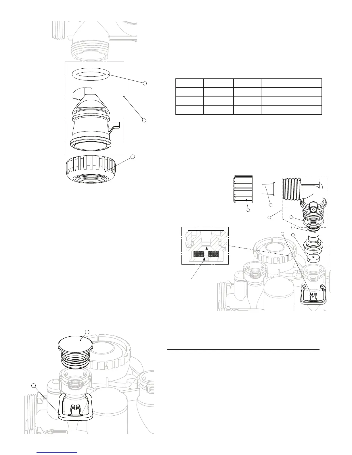
Water Meter, Meter Plug and Mixing Valve
Drawing No. Order No. Description Quantity
1 V3151 WS1 Nut 1” QC 1
2 V3003* WS1 Meter ASY 1
3 V3118-01 WS1 Turbine ASY 1
4 V3105 0-ring 215 1
5 V3003-01 WS1 Meter Plug ASY 1
6 V3013 Mixing Valve Optional
*Order number V3003 includes V3118-01 WS1 Turbine ASY and V3105 O-ring
215.
3
4
5
1
2
6
THIS WATER METER SHOULD NOT BE USED AS THE PRIMARY MONITORING DEVICE FOR CRITICAL HEALTH
EFFECT APPLICATIONS.
NOTE: A water meter is not applicable for a TC control valve.
WS1 & WS1.25 Drawings & Service Manual Page 17
Water Meter, Meter Plug and Mixing Valve
Drawing No. Order No. Description Quantity
1 V3151 WS1 Nut 1” QC 1
2 V3003* WS1 Meter ASY 1
3 V3118-01 WS1 Turbine ASY 1
4 V3105 0-ring 215 1
5 V3003-01 WS1 Meter Plug ASY 1
6 V3013 Mixing Valve Optional
*Order number V3003 includes V3118-01 WS1 Turbine ASY and V3105 O-ring
215.
3
4
5
1
2
6
THIS WATER METER SHOULD NOT BE USED AS THE PRIMARY MONITORING DEVICE FOR CRITICAL HEALTH
EFFECT APPLICATIONS.
NOTE: A water meter is not applicable for a TC control valve.
3
2
Page 14 WS1 & WS1.25 Drawings & Service Manual
Re ll Flow Control Assembly and Re ll Port Plug
Water
Flow
Proper RFC orientation
directs re ll water ow
towards the washer face
with rounded edge and text.
Drawing No. Order No. Description Quantity
1 V3195-01 WS1 Re ll Port Plug Asy
This part is required for backwash only sys-
tems
2 H4615 Elbow Locking Clip 1
3 JCP-P-6 Polytube insert 3/8” 1
4 JCPG-6PBLK Nut 3/8” 1
5 H4613 Elbow Cap 3/8” 1
6 V3163 0-ring 019 1
7 V3165-01* WS1 RFC Retainer Asy 1
8 V3182 WS1 RFC 1
9 V3330-01 WS1 Brine Elbow Asy w/RFC 3/8" 1
Not Shown V3552 WS1 Brine Elbow Asy w/RFC 1/2" Option
Not Shown H4650 Elbow ½” with nut and insert Option
*Assembly includes V3182 WS1 RFC.
9
 Loading...